Summary:

This year for my Christmas lights project I decided to do something a bit different. Rather than setting up a more elaborate temporary setup, though last year's morse code tree was very fun, I decided to plow the time into making a control box that I can hopefully use year to year. It's got an 8-relay board (hooked up to AC) for output, an Ardunio UNO for control and a phone-cord jack for user IO. Getting everything in a nice box ended up taking a fair bit of time, so for this year I just ran a bouncing ball pattern. In future years though, there should be some great possibilities for more interesting patterns and some kind of IO board (maybe with suction cups) to interact with the tree.
For the actual lights, I cut 6 strands of old colored lights in half and fit each one with a tail of wire and a deans connector in place of a power plug. This let me create bands of light moving up the tree, which could be controlled from the box. For this year, I just ran them with a bouncing ball pattern (2 balls, one moving every 2nd tick and the other every 3rd) but in future years there's some potential to do something more complex, or maybe revisit morse code in a big way.
Hopefully I don't have to spend too much time in the guts of this box in the future, but just in case the build log is below. I mostly wrote it for my own sake, so if you're considering a similar build feel free to drop me a message and I'll try to answer any questions you have and give you an update on how it has held out to date.
Stats:
The box has 8 deans outputs to mains controlled with an Arduino and 8-relay board. The system can support up to 10 amps per output, and should be limited to about 15 amps overall. In addition to the standard Arduino USB input, I added a phone jack hooked up to 2 analog and 2 digital pins on the Arduino. For now I'll use the box to run passive patterns (getting pretty close to Christmas day), but in the future that should let me make a control board, or push patterns over Software Serial.
LINKS:
No idea why this would be relevant...
Pictures:


Build Log:
1) After a bit of scrounging, I came up with the following to run this years tree. With the exception of the screws everything is from e-waste or the remains of a prior project. That said, most of this stuff can be gotten pretty easily on a=Amazon or Ebay if needed.

Eight-Relay breakout board.
Arduino Uno.
Deans Connectors (8 pair)
Power Entry Module.
5v power supply (for Arduino)
Screws and washers for mounting.
Christmas Lights.
Project Box.
2) Remove the PEM from a sacrificial computer power supply. It's worth hanging onto the grounding wire, if it looks well made, but re-soldering the power and return wires (with heat shrink) is well worthwhile.
3) Cut each of three LED strands in half (make sure to cut between segments so there's still a return path) and solder the deans connectors (male) onto the end.
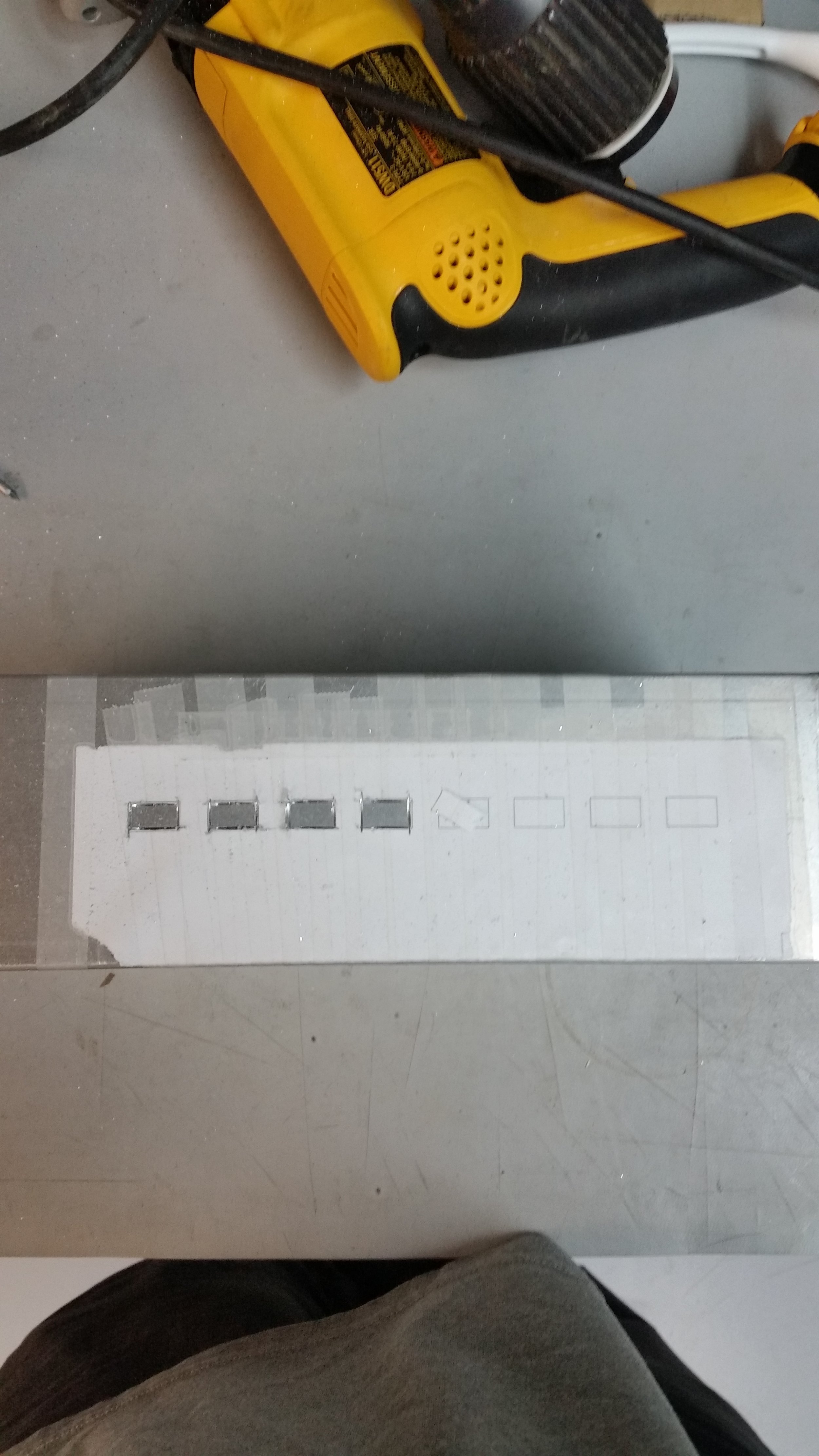
A single layer of scotch tape should be enough to prevent the paper from tearing.
4) Cut a rectangular hole for the PEM and 8 smaller holes for each of the 8 female deans connectors. if you've got access to a mill that's definitely the way to go. Otherwise, use inkscape (or similar) to print out the cuts on a piece of paper, and secure it to the box. Then use a dremel and file to cut each hole.
5) Lay out the Arduino and relay board then use a punch (nail) to mark the hole locations and drill then. If you don't have a drill it's possible to get by with a nail and some files.

6) Next, test-mount the Arduino. If the project box is metal, use some sort of standoffs (I used washers) to keep the Arduino from shorting against the case. Then, use a pen or knife to mark around the USB port. Take the Arduino out and cut that with a dremel so the Arduino's usb port can be accessed from outside the case.
7) Test fit the the relay board, and cut lengths of black wire to run from a deans connector to each of the plug holes. Then, cut lengths of red wire to run from the deans connector to each of the relay units, and from each of the relay units to each of the plug holes. Strip 5mm off the end of both ends of each wire.
8) Solder the black and red (deans to relay) wires to a male deans connector. I am using + to mean hot, but it doesn't matter as long as you are consistent. Before soldering, plug the deans connector into its female counterpart so the tines don't shift if the plastic melts. (A problem on counterfeits.)
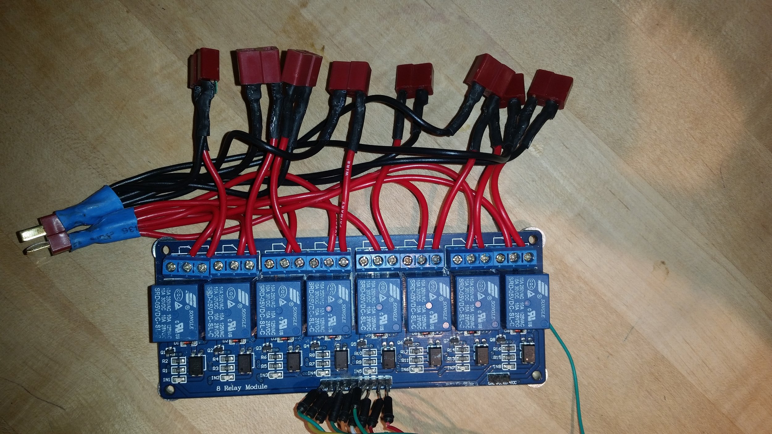
9) Connect one red wire from the bundle to the common pin of each relay. Then connect one of the short red jumper wires to the normally open pin of each relay. At this point, it is worth doing a continuity check with a multi-meter to make sure all the screw-terminals are connecting properly.

10) Solder one of the black wires, and one of the red jumper wires to each of 10 female deans connectors. At this point, each female deans connector should be connected to the male deans connector pictured above, via one red and one black wire, with a relay in the power path on the red side. As a side note, the relays determine the per output maximum current (10 amp in this case) while the male deans connector determines the max combined current.
11) Fit the Arduino to its mount holes, and mark the outline of the programming port (probably a USB B) with a pen or scribe. Then cut a hole to access the port. I used a dremel and metal file from the inside, but you could also measure and cut from the outside.

12) At this point, It's time to get the PEM set up. Solder two sets of female deans connectors to the L and N terminals. One of these provides power to the outputs, while the other will be used to run the 5v power supply. If you pulled your PEM from a computer power supply, the pre-existing ground wire is probably fine, but if it seems sketchy, it might be worth replacing that too.
13) Next, mount the PEM. You may want to drill some mounting holes or use epoxy to hold it in place. Make sure to hook up your grounding post. Double nuts is a good idea, but as long as you are using lock nuts (or lock washers) that should be fine.
14) With the PEM in place, decide how you want to mount your low voltage supply. In this case, I used an old 12v supply I pulled from E-waste and mounted with double-stick tape. Whatever you decide to use, test fit it and then attach a male deans connector to the AC side, and some jumper wires to the low voltage side.
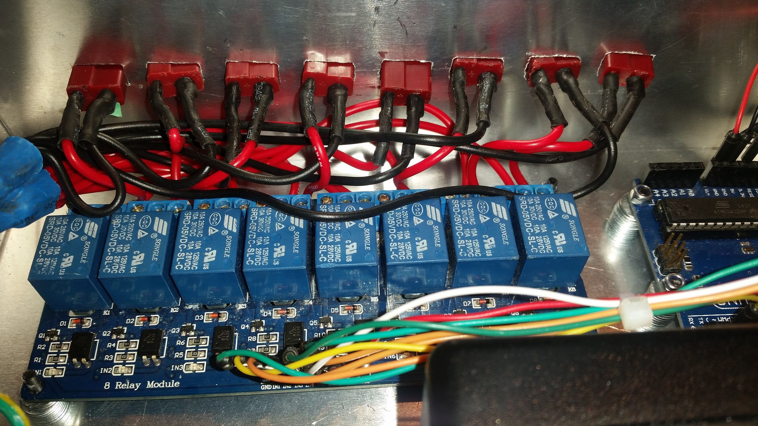
15) At this point, start assembling the box to the degree you can. There's still one more hole left to make (for the control input), but I think it makes sense to put that in once the wiring is in place. Start off by mounting the Arduino and relay board. Once both of those are in place, route the control wiring. As a side note:for this build most of the wires were already soldered from a previous project and I didn't want to risk heating up the pins again. That said, if your'e doing this with a new relay board I'd go with male-female jumpers rather than soldering.

16) With the wiring more or less in place, take your input port of choice (I used a phone cord extender cracked in half) and sketch itss outline on the outside of the box. Make sure that its wires will play nice with the rest of the cabling. Then, dremel and sand the hole to size.
17) Press fit the your output connectors and signal connector into place.
18) Superglue and epoxy the output and input connectors in place. Depending on your wiring, the deans connectors may not want to stay straight. This isn't the end of the world, but to make sure they are all more or less lined up I find it works well to superglue each one individually and then epoxy in batches.