Overview:

Our transmission design calls for 36 machined parts, generally held to 2 thou tolerances, with the majority being either rotary table or lathe parts. We were generally able to machine exactly to spec. However, in a few cases we had to modify the design slightly to accommodate issues with tooling or available stock.
Note: In the interests of completeness I have included a summary of how we fabricated each part in the transmission. However, I spent the vast majority of my time working on our rotary table parts and as a result those are described in much greater detail.
General Reflections:
By far the biggest lesson I learned from this project is that there is a very large per-part learning curve. Even completing operations I had done the same day the time to re-cut a part was generally about 1/2 to 1/3 the time to cut it the first time around.
reamers and boring bars should be checked for wear before use. One of the big issues we had throughout the project was discovering that many of the shop reamers cut substantially oversize. Testing beforehand would have caught this and eliminated some re-work.

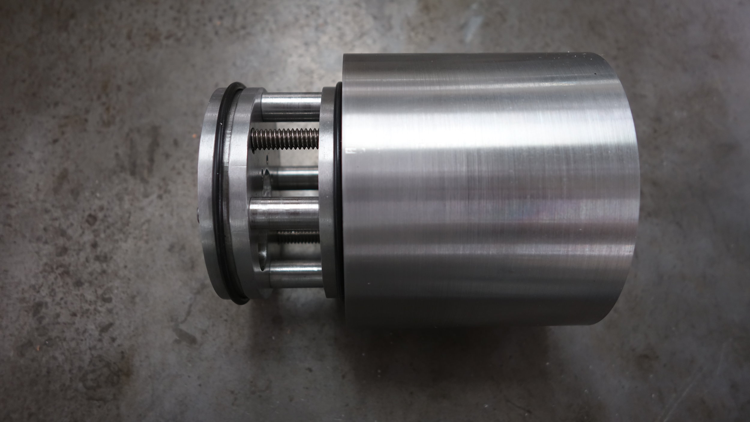
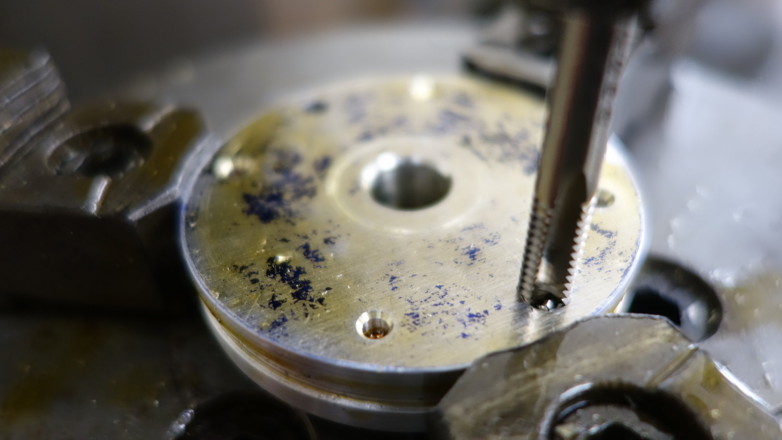
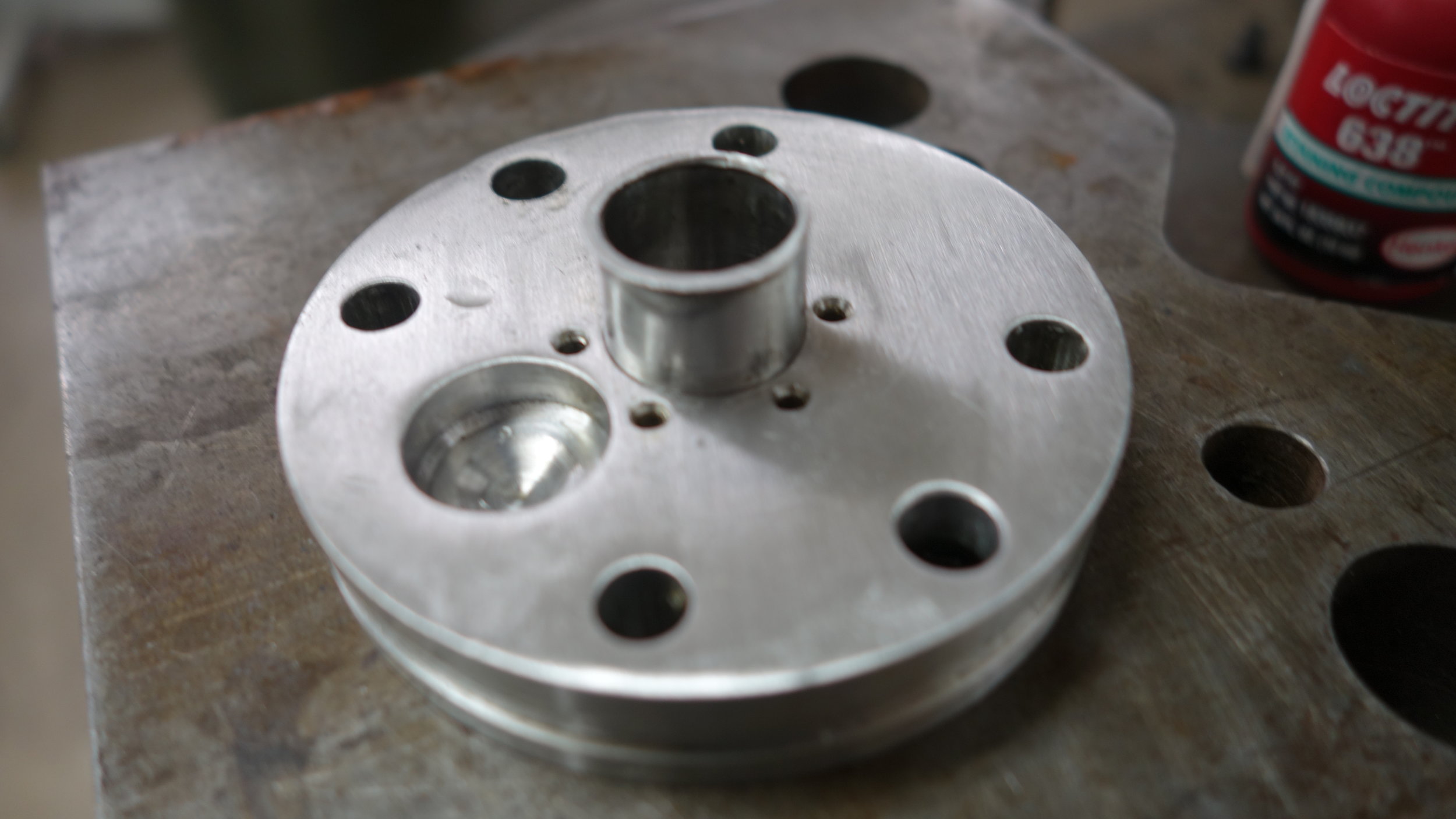
The inner face of an outer alignment plate. Note the transfer shaft pocket and 6 tapped holes.
Alignment Plates:
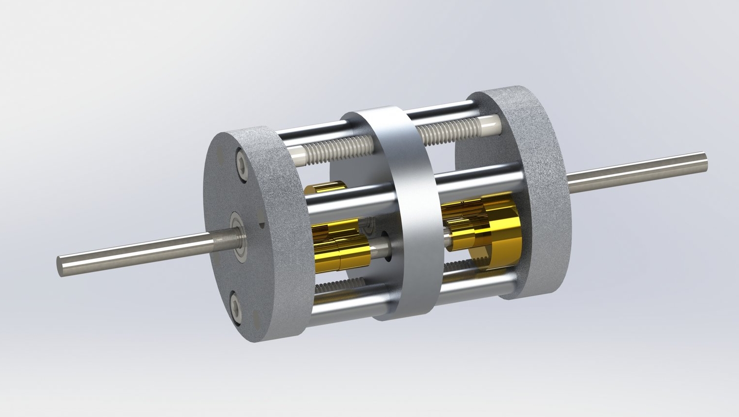
The alignment plates hold our gear shafts in alignment, and are our most complicated rotary table parts. All three plates are largely identical. However, there are some substantial differences in terms of mounting hardware and shaft fits (see below).
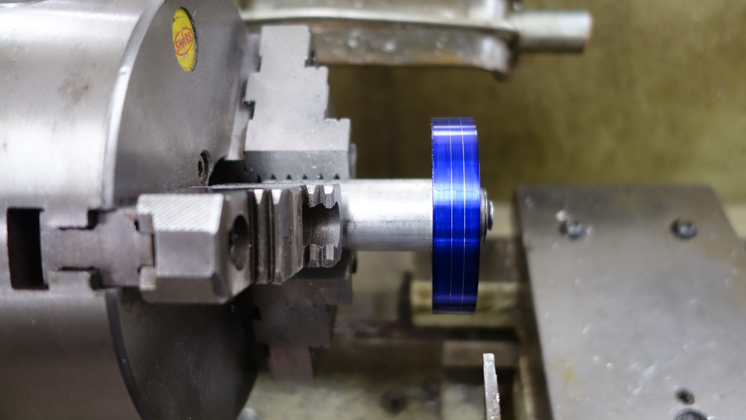
Since this part is internal, we decided to go with a finishing wheel polish. We had originally used a sand blasted finish, but found it to delicate for internal parts.
Before starting machining of any kind we first set up the rotary table. The table itself, chuck plate, and chuck all had to be centered to +0.5 - 0.5 thou. Fortunatly, we were able to keep the fixture set up throughout the project.
For the most part the alignment plates were machined according to plan. However, we did open up the center plate's alignment holes to a clearance fit in order to ease assembly.
Notable Features:
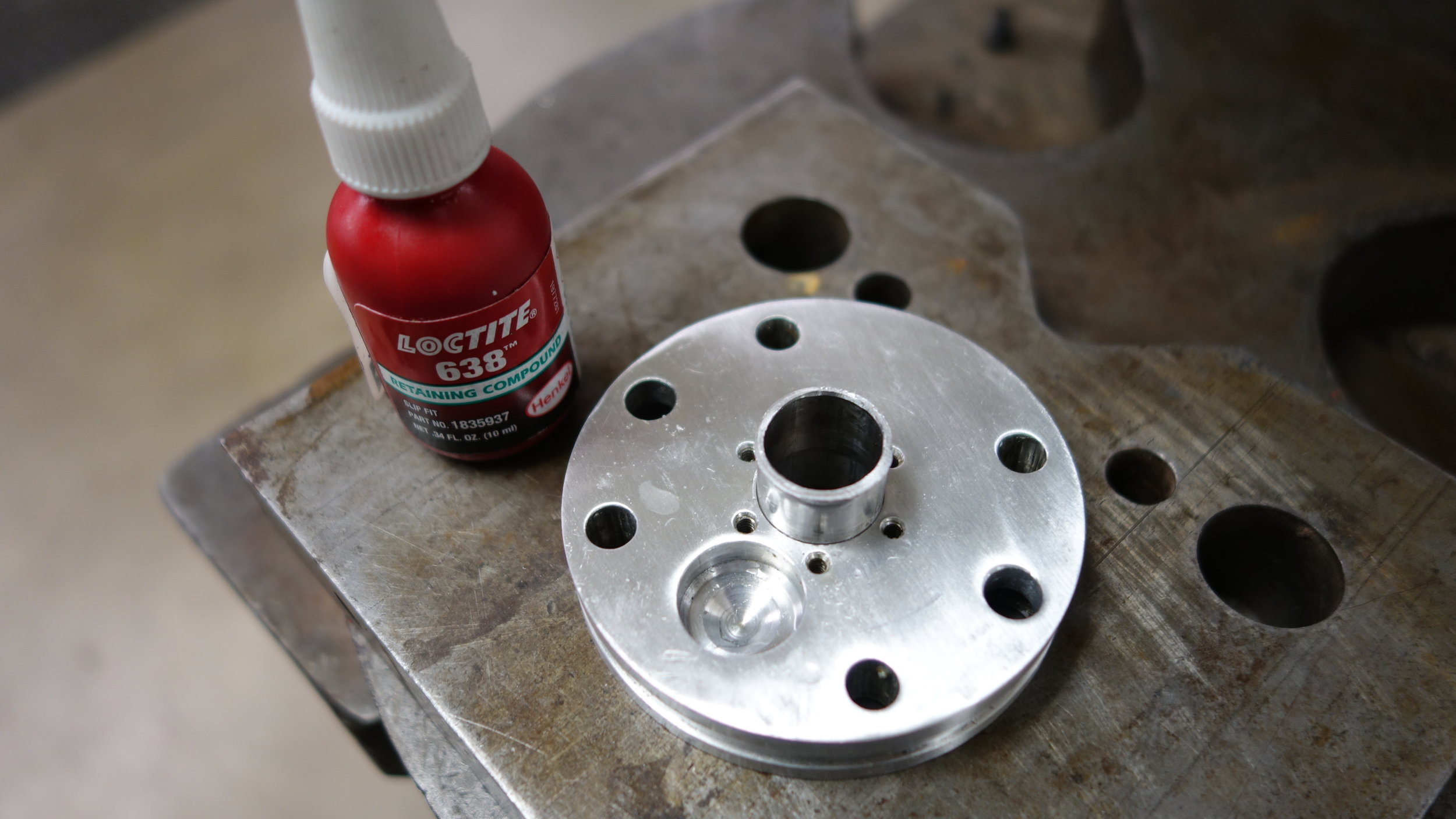
Groove for a -145 compression fit o-ring.
Slip fit holes for the alignment shafts.
Press fit holes for the IO shaft bearings.
Press fit pockets for the transfer shaft bearings (ends).
Clearance hole for small transfer shaft gear (center).
1/4 - 20 countersunk holes for tension screws (ends).
1/4 - 20 tapped holes for tension screws (center).
4-40 tapped holes for end plate screws (ends).
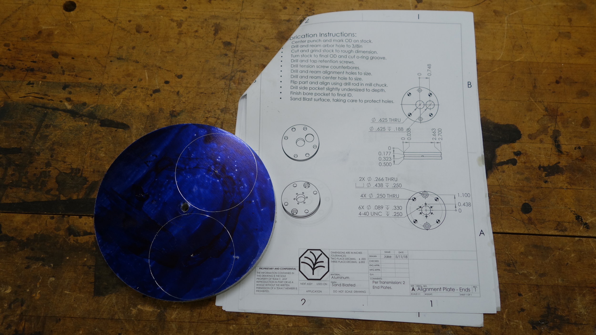
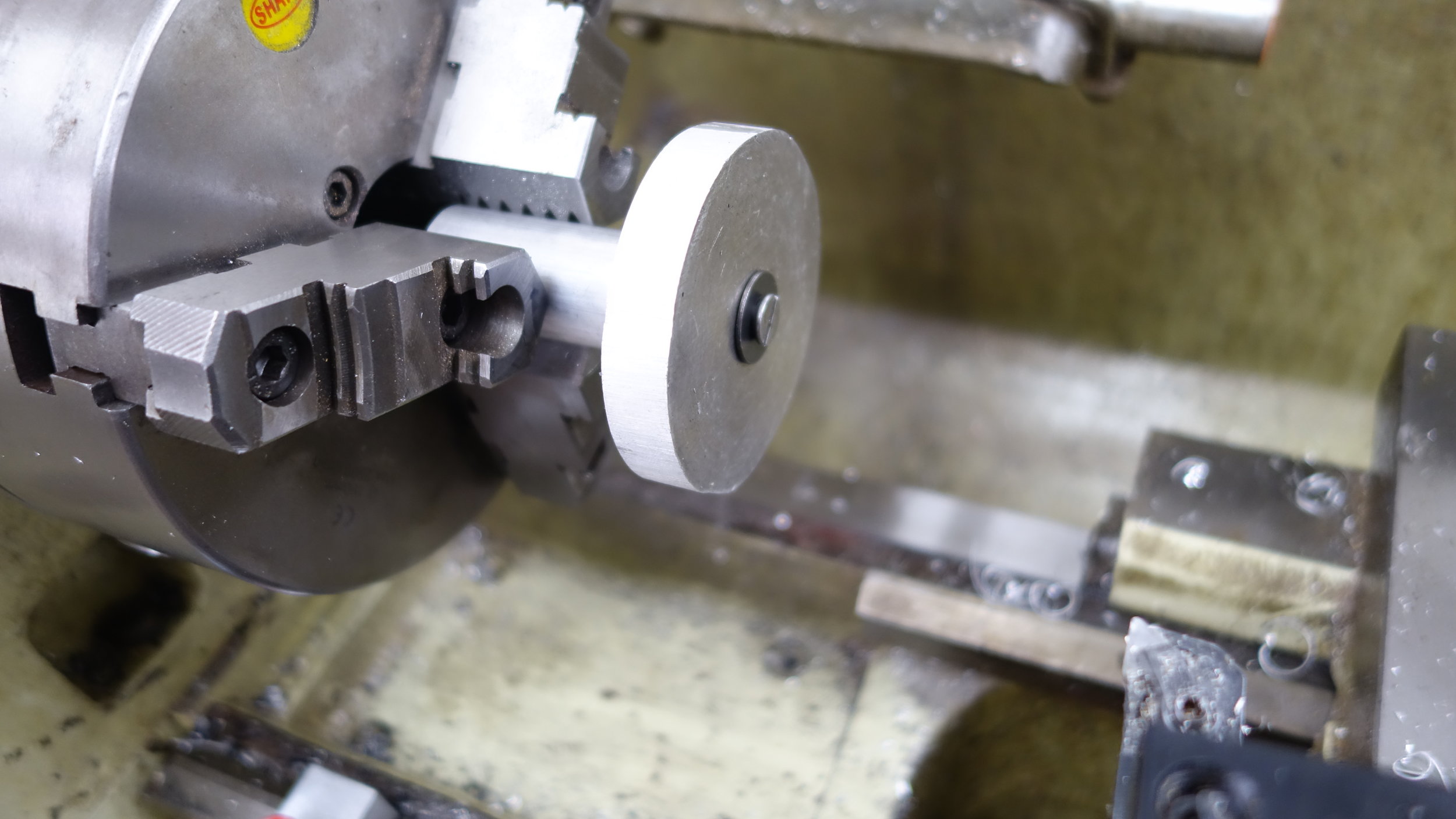
Machining Process:
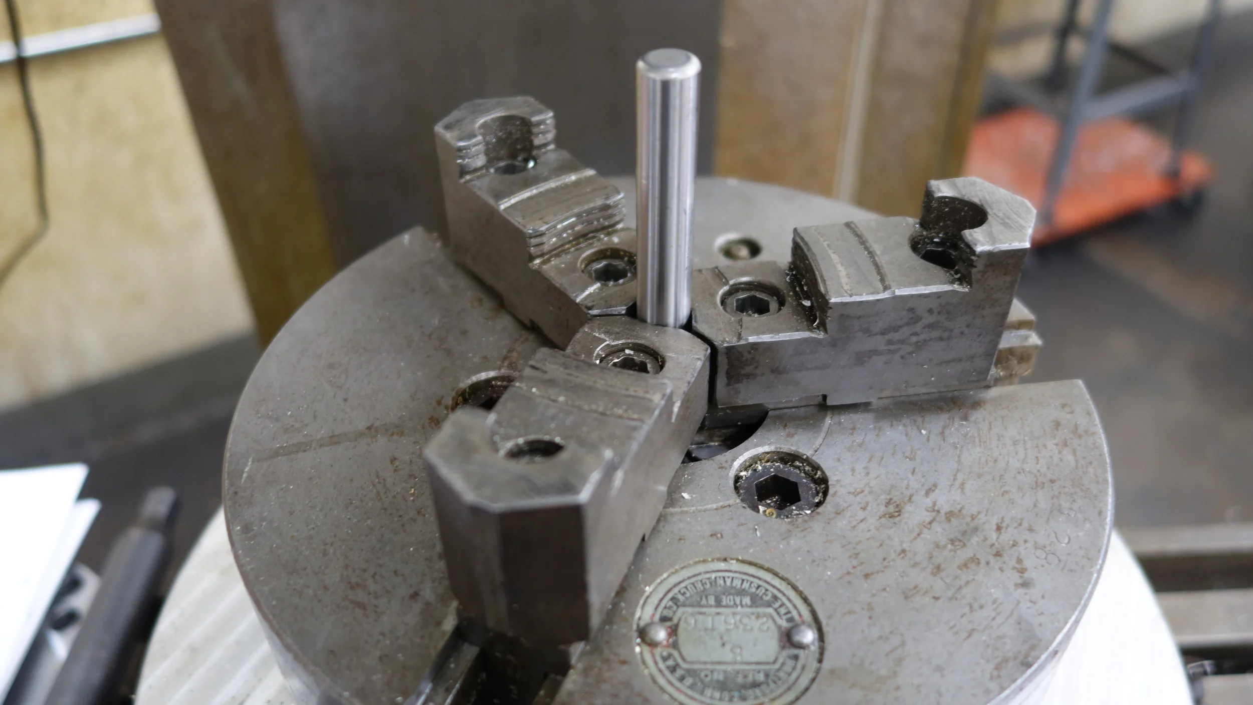
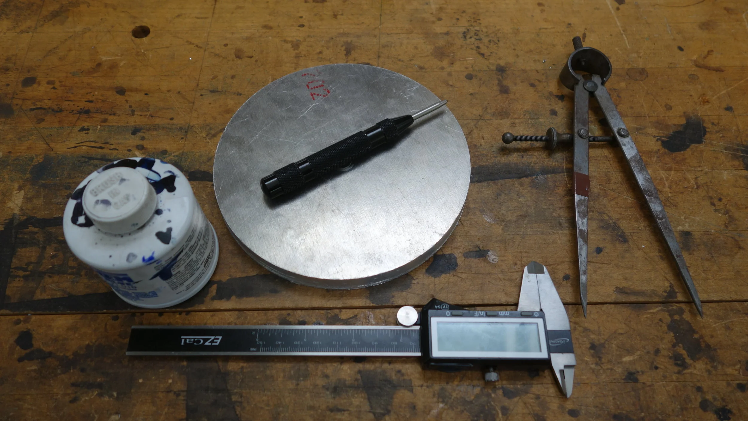
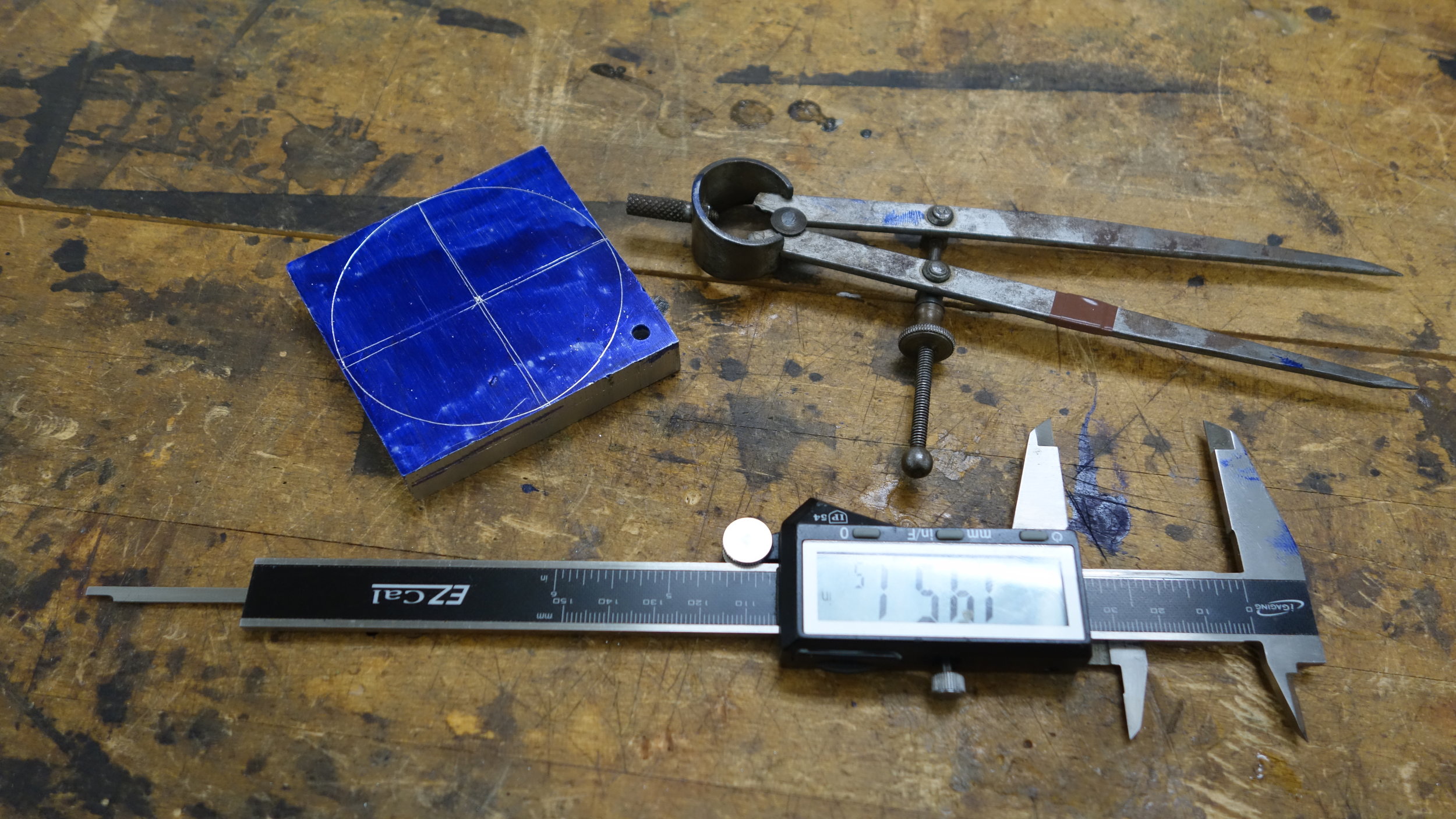
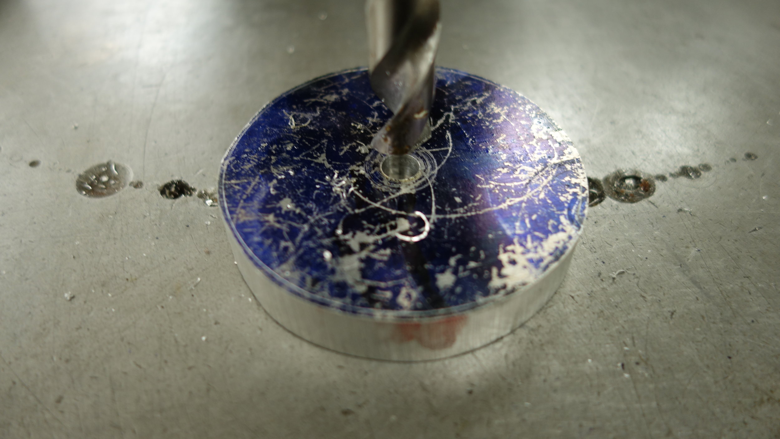
These parts were machined in two parts. First, the rough shape was marked, sawed, and ground out of sheet scrap. The rough center of each piece was then drilled and reamed to accept a 1/2" arbor. This allowed us to turn the parts to their final dimensions and add the o-ring groove. Once the part was at it's final dimensions, we moved it to the rotary table. We then machined all of the various holes, threads, and pockets on the mill. For the end plates one of the alignment holes was used as a reference to ensure consistent angular dimensioning between sides.
We had a huge amount of trouble with the shop reamers for this project. In particular, we found that most of both the 5/8 and 1/4 shop reamers run several thou large. For the reamed 1/4" holes we used a 1/4" nominal reamer and sanded the holes to size. The damaged 5/8 reamer was only used for one hole, and in that case we press-fit a plug in place, and re-drilled/reamed the hole using sharper tooling.
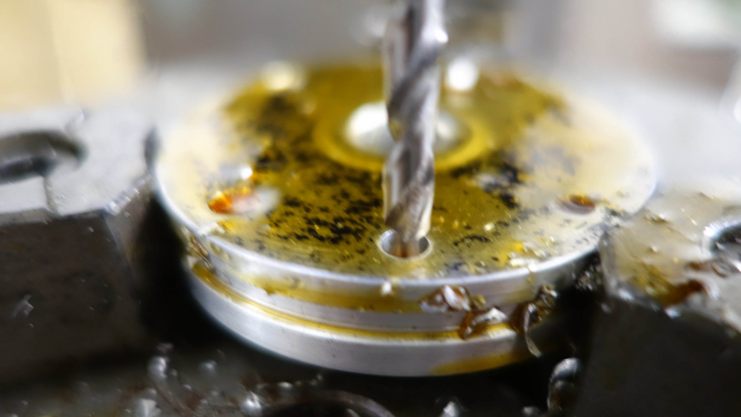
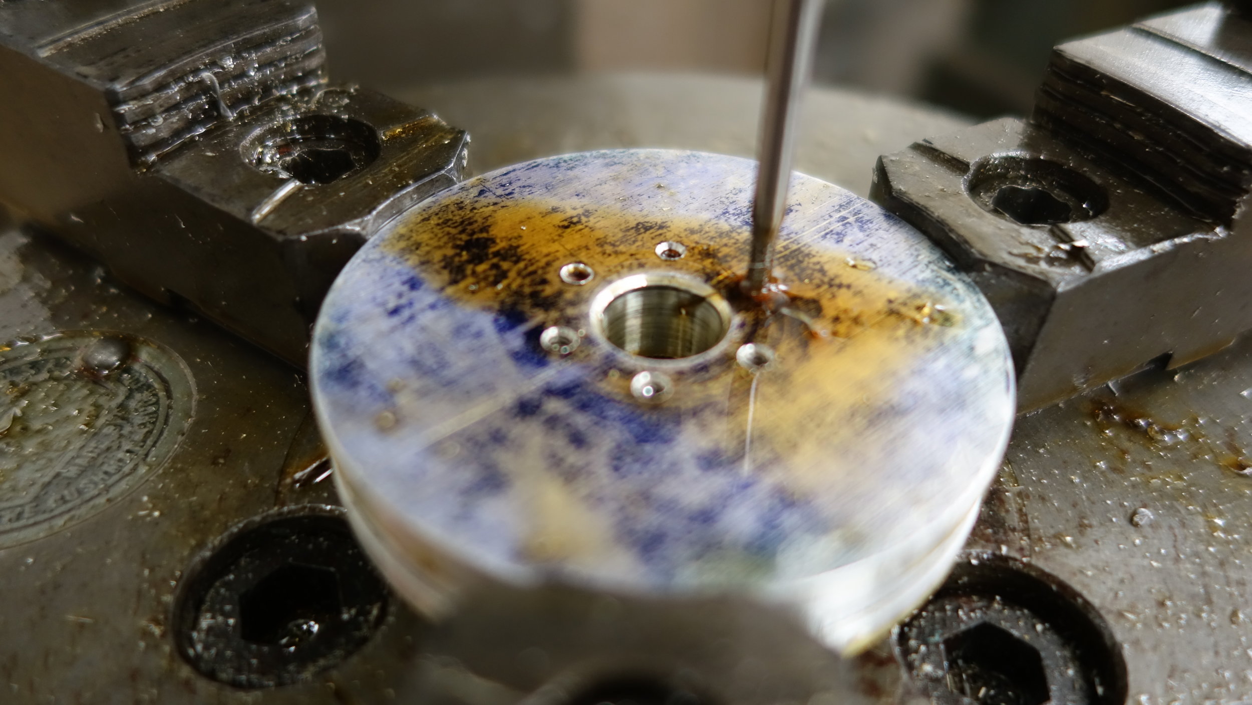
That time we needed a smaller hole so we pressed a plug in place and re-drilled it. (Worked fine, would do again).


Outer Casing:
The outer casing was machined from a piece of 3.5in aluminum tubing with 3/8in walls. The ID and OD were then turned to ensure they were concentric, and the ID was taken down to comply with the requirements for a -145 compression fit. Once the housing stock had been fabricated six 4-40 holes were trilled and tapped in each side of the part using the rotary table. To ensure good alignment the entire inner module was assembled along with both end plates, and the second set of holes were located using a center punch (with the rotary table to enforce circle diameter and angular spacing).


End Caps:
The endcaps serve two purposes, they protect the internals from contamination, and they prevent the inner transmission assembly from spinning relative to the casing. Fundamentally though they are mostly an aesthetic component. Each blank was first roughed to size on the bandsaw and then turned to size on the lathe. The socket head pockets and bearing relief were then cut and the parts were polished to a mirror polish.


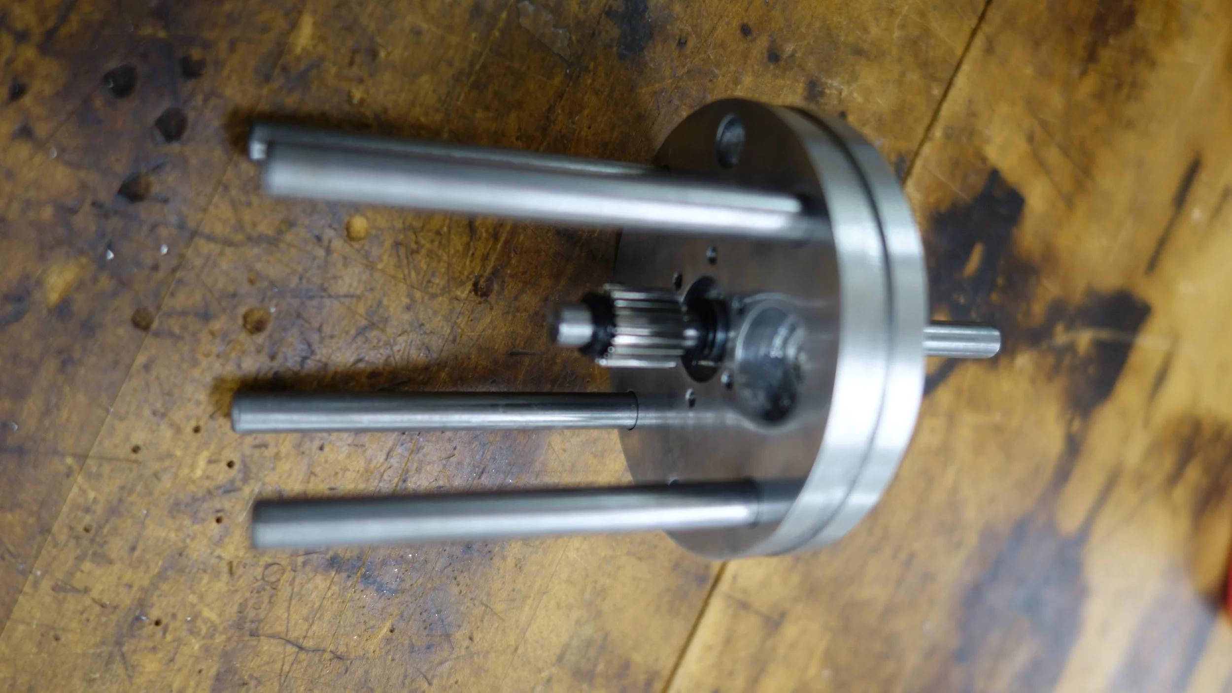
Alignment Rods:
The alignment rods stretch from one end-plate to the other suspending the central alignment plate between them. The rods are made of O1 tool steel, and were machined to length on a lathe and then sanded slightly to a firm slip fit.
Spacers:
The spacers hold the axial spacing of the plates. They are composed of 5/8in aluminum and were cut on the lathe in two groups, both internally consistent to about 0.5thou. The ID was taken up to 9/64ths in-order to ease assembly.
IO and Transfer Shafts:
The IO and transfer shafts were cut out of 0-1 tool steel, and were designed to fit snugly between their constraining plates. The retention clip grooves were cut with an appropriate carbide groove cutter, and the overall length was turned on a lathe. Small flats for each set screw were cut using a collet block and machinists jack on a vertical mill. We found that the use of a sharp (new) endmil was non-optional for cuttiong O-1 with good tolerances.
Base Plate:
The base plate was fabricated out of the same 7/16in stock as the base plate clamps. It was squared and then the holes were drilled. The dimensions for this part were largely constrained by the size of our clamp stock, and the hole pattern specified by the test apparatus. Once fabricated, all of the base and clamp components were sand blasted.
Base Plate Clamps:
The base plate clamps were one of the most fun parts to create. First the shape was sketched on scrap with a compass. Then, they were clamped to a rotary table and the curved sides (OD and ID) were cut. We had originally planned to use superglue for that process, but after speaking with the shop foreman decided to use two different clamping setups instead.
Once the outer profile had been milled, we clamped the parts in one of our Bridgeport clones, and used the rotating head to cut the two angled pockets. After a bit of debate, we ended up using three setups per part with a work stop, rather than moving the head for each part. That worked well, and I would use that approach again.


Clamp Riders.
The clamp riders were cut with a pair of bolt cutters and then sanded/hammered to length. This worked well enough, but if I were to do the project again I would try to hold both the hole depths and the clamp rider lengths to tighter tolerances.