The Frog (our amphibious robots) electronics were one of my personal favorite parts of the project. We didn’t get both robots quite set up by the competition itself, but designing the system was a ton of fun. Working with water was a particularly interesting challenge.
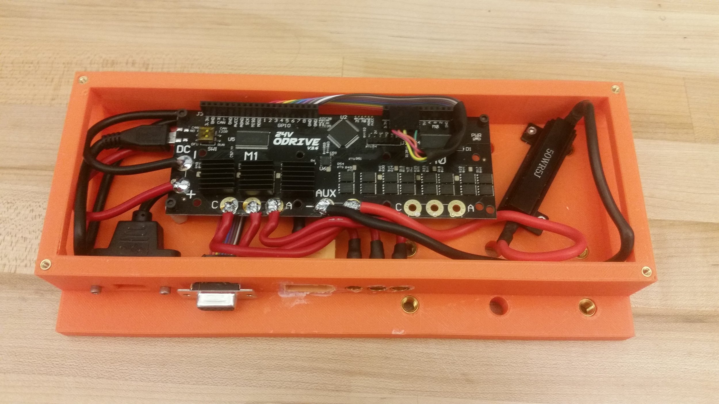
At a high level, the system works as follows. Each robot is powered by two batteries, one per side, that are shared between the land and water drive systems. The batteries are connected by relays to distribution boards, allowing the main drive power to be disabled between matches (or to reset the motor drivers). The motor controllers are then controlled by an Arduino nano through a PCA9685.
Note: This project / write up was actually completed several years ago. It’s just taken me a little bit to get around to posting it.

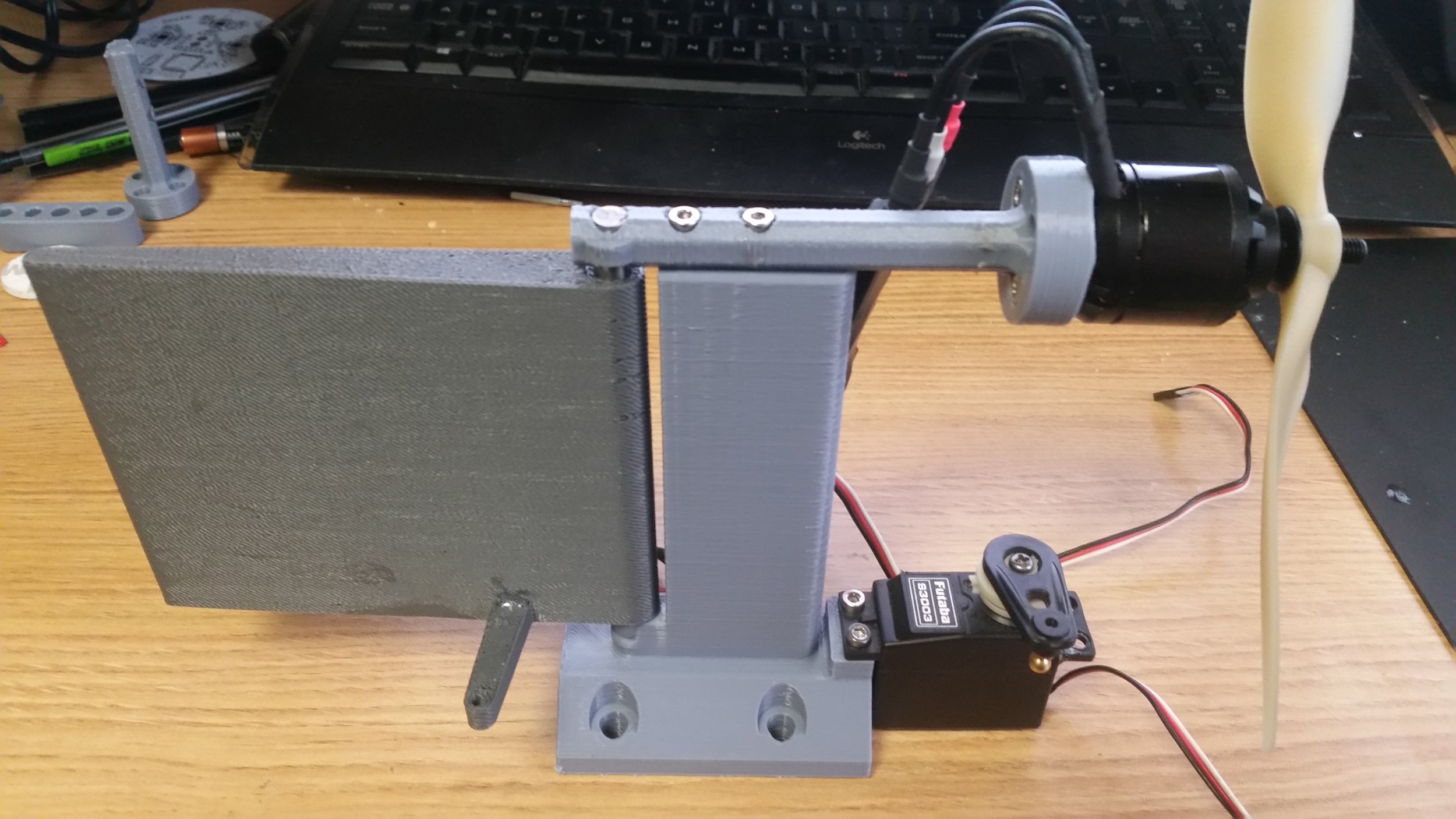
Our prototyping board during first term. Very convenient, but not exactly waterproof…
Motors and Drivers:
We decided early on that we wanted to use brushless motors for the mobility systems. Partly that was driven by a desire to learn about brushless motors, but mostly we were hoping for a speed advantage.
We selected our motors by first determining the speed we needed each to run at (dictated by the cavitation speed of the props for water, and by our desired top speed for land). Then, once we had a KV rating for each motor type we selected the most powerful model we could find under about 30 dollars. Since this project I’ve learned quite a bit more about brushless motor control and would recommend actually computing the required torque’s/currents, but I will say that that method worked quite well in practice. The motors we selected can be found below. Note that for the water motors, we choose different motors for the second robot based on what was on sale. The land and water motors both performed well (though the water motors were massive overkill) and I plan to re-use these motors when I have similar torque and speed requirements in the future.
Notable Parts:
Land Motors: Turnigy G32 600kv motor [Link]
On quirk of the ESCs we used is that they require fairly specific inputs on startup, or they will fail to arm. This is common on a lot of hobby ESCs as a way to prevent crashes or injuries on powerup. Our eventual solution to to this problem was to have the arduino reprogram each ESC to our desired settings whenever the power relays were cycled. This was probably slight overkill for normal operations, but was very handy for debugging and I will certainly include similar features on future robots.
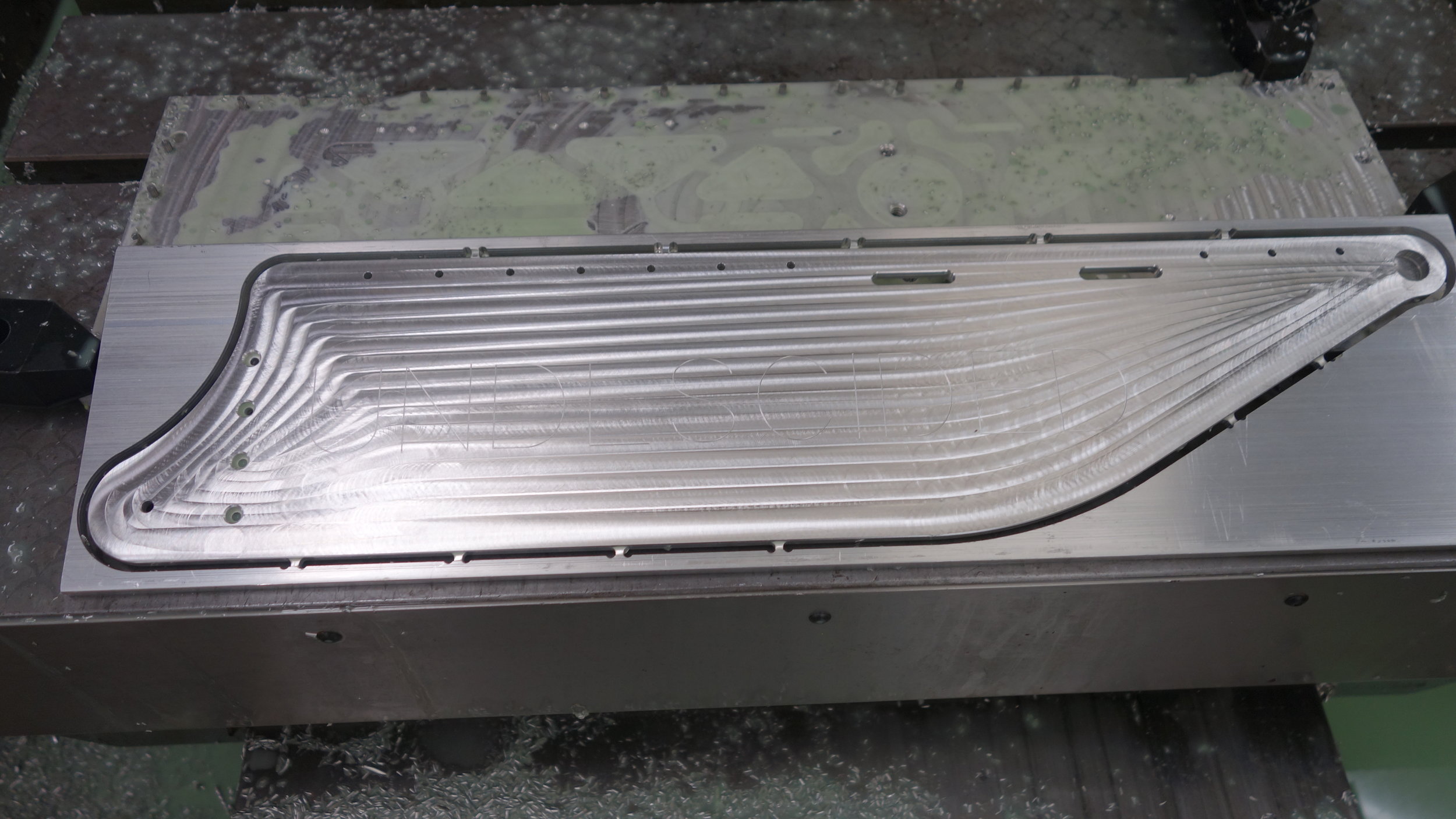
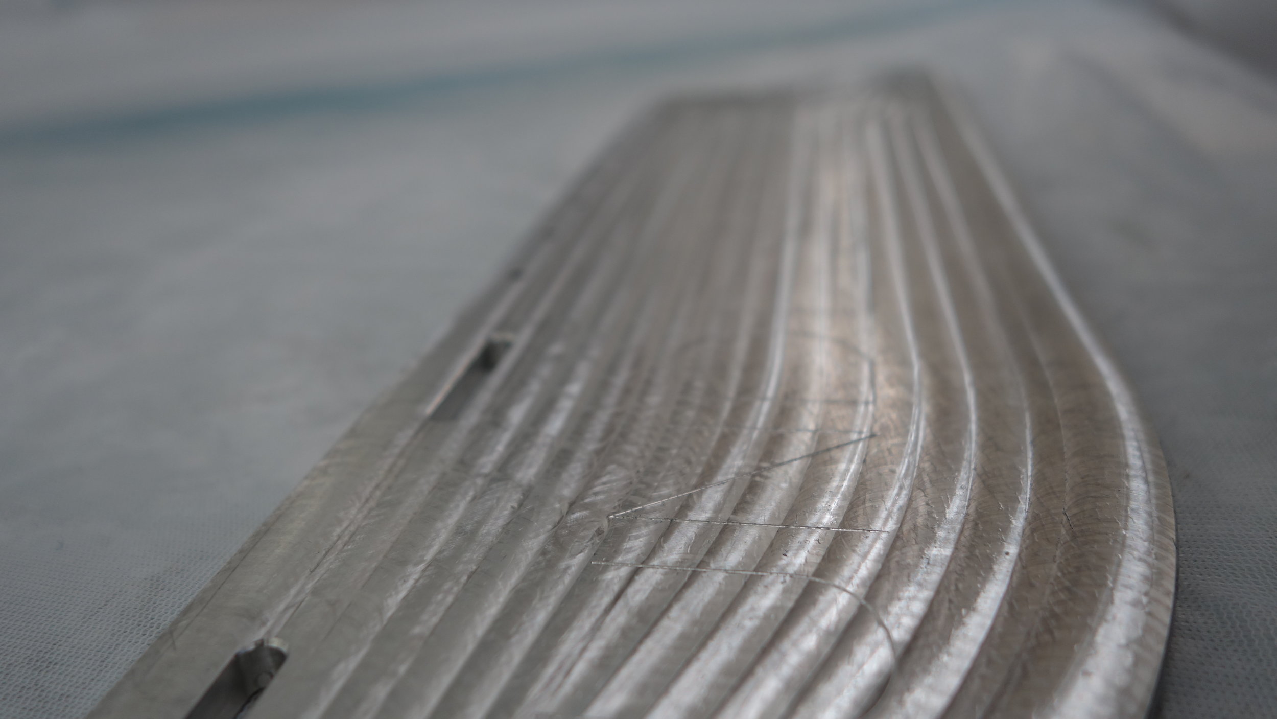
The ESC’s we used were nominally water cooled. We designed out first robot to use a tap off the jets for cooling the water ESC’s, and a closed water loop (with a heat sink chamber milled into the rear plate) for the land ESCs. In practice we discovered that no water cooling was needed for our current draws, so we dropped the jet taps and heat-sinking geometry from our second robot.
Ball Handling:
The ball handling electronics ended up being a rush job. Each of the Frogs had a pair of custom made linear actuators driven by a brushed DC motor. We did not have time to develop a driver board, and so instead we selected a Polulu board (model unknown) from a bin in the shop. This worked fine on the bench, both under central control, and when set up to run off a separate receiver, but proved unreliable in the competition when exposed to water.

Waterproofing:
Our electrical systems had two lines of defense against water. First and foremost, all of the core electronics were housed inside sealed waterproof containers. The batteries were also housed in a waterproof 3D printed container, with the distribution boards acting as pass-through bulkheads. This worked well on the whole, although some of our systems required more tuning that was practical day-of. Secondarily, all of the critical components were waterproofed with nail polish on a board level. That was largely unnecessary, but also proved highly effective during testing.
I would, unfortunately, be remiss if I did not note that during the actual competition some of our components were not yet enclosed in waterproof boxes, and failed as a result. In particular, the drive system for the ball handing was external to the main control module, and proved particularly vulnerable to water.
Power supply:
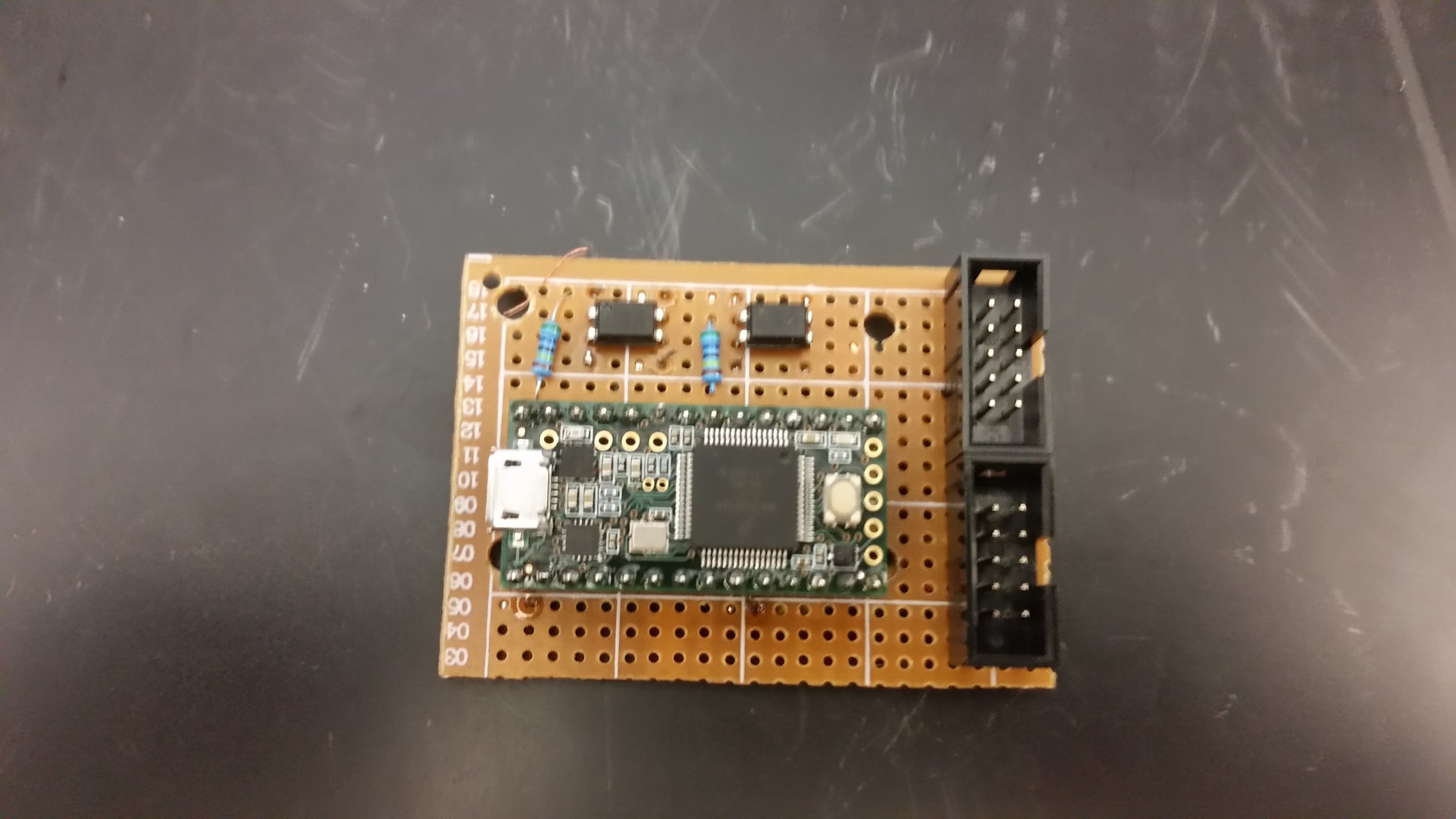
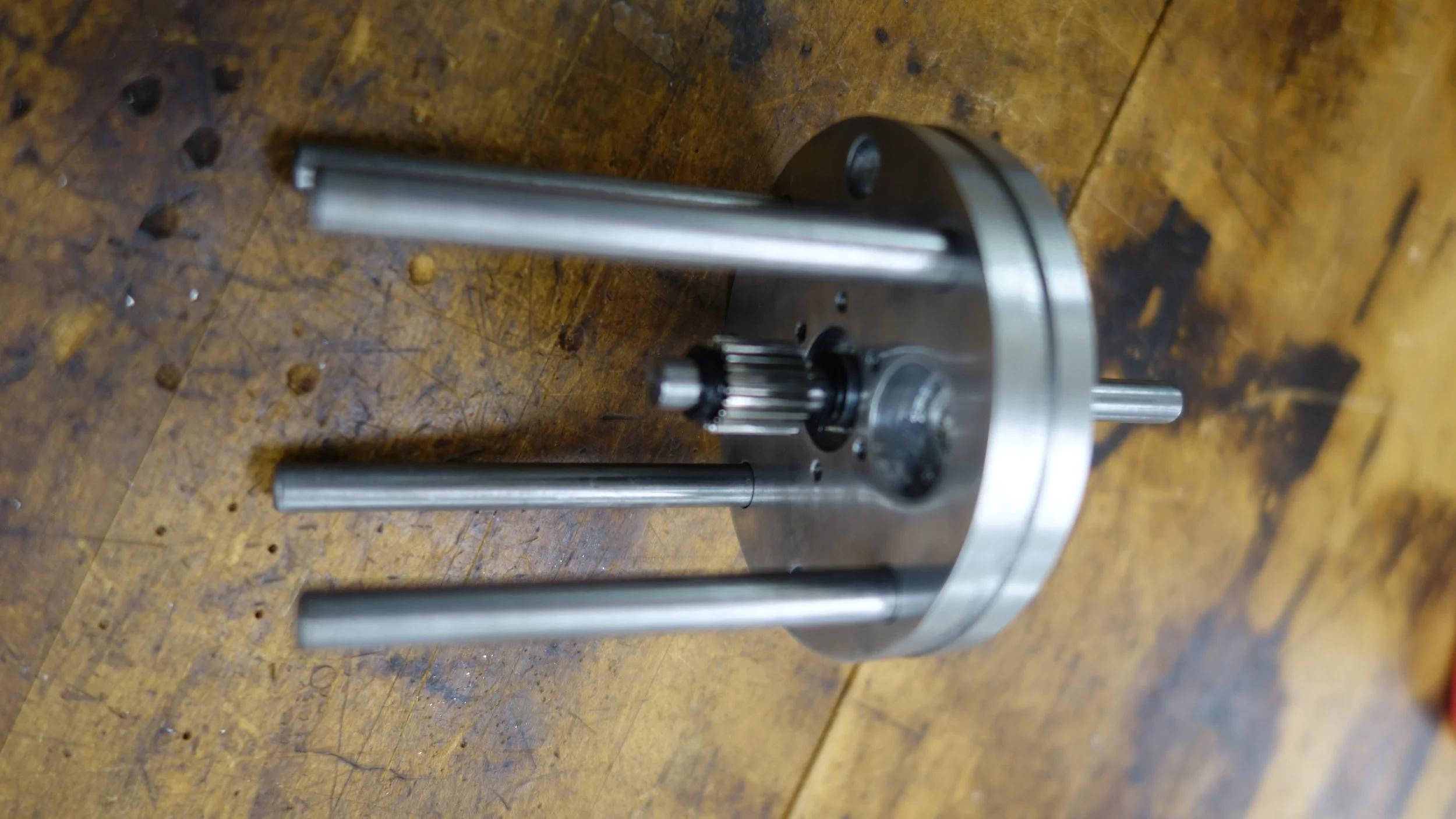
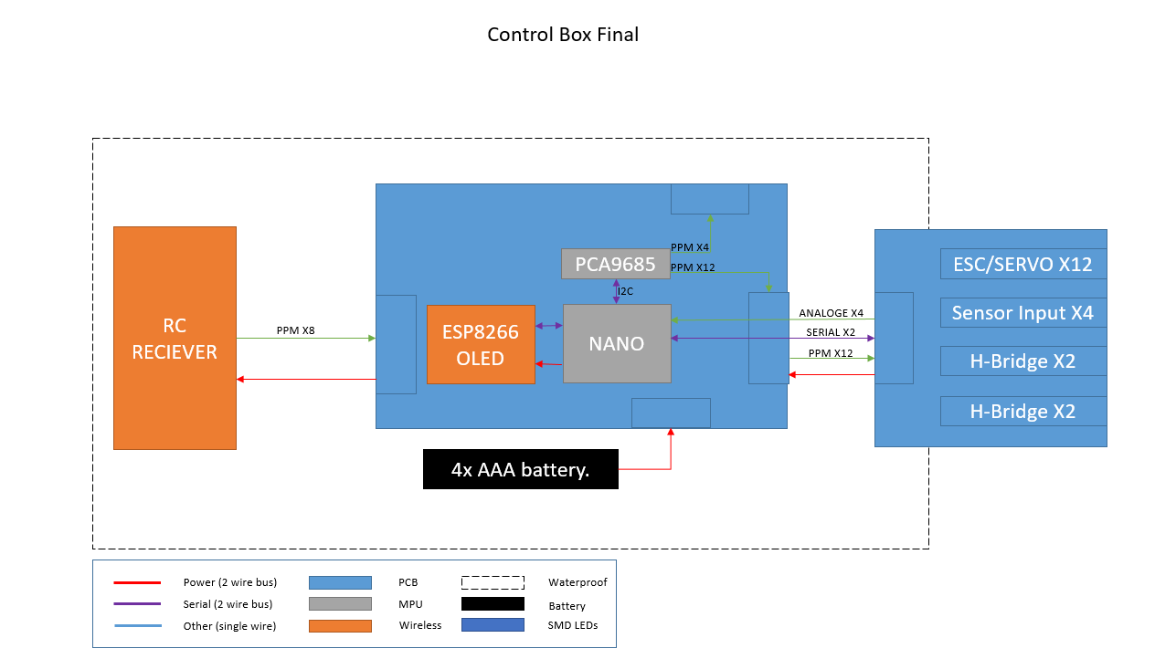
The control module had it’s own internal quad of AAA batteries to power the display, driver, and nano. Those batteries were connected to the main PCB through a normally open reed switch. This let us enable and disable the robot by connecting a magnet to the outside of the control housing. Under normal (no wifi) use the control module batteries had about 12 hours of life. To make it a bit easier to tell when we were getting into the danger zone an ESP8266 with OLED screen was added to provide a voltage readout.
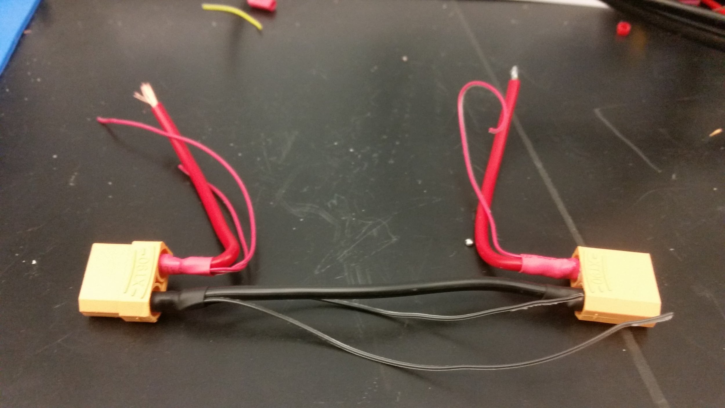
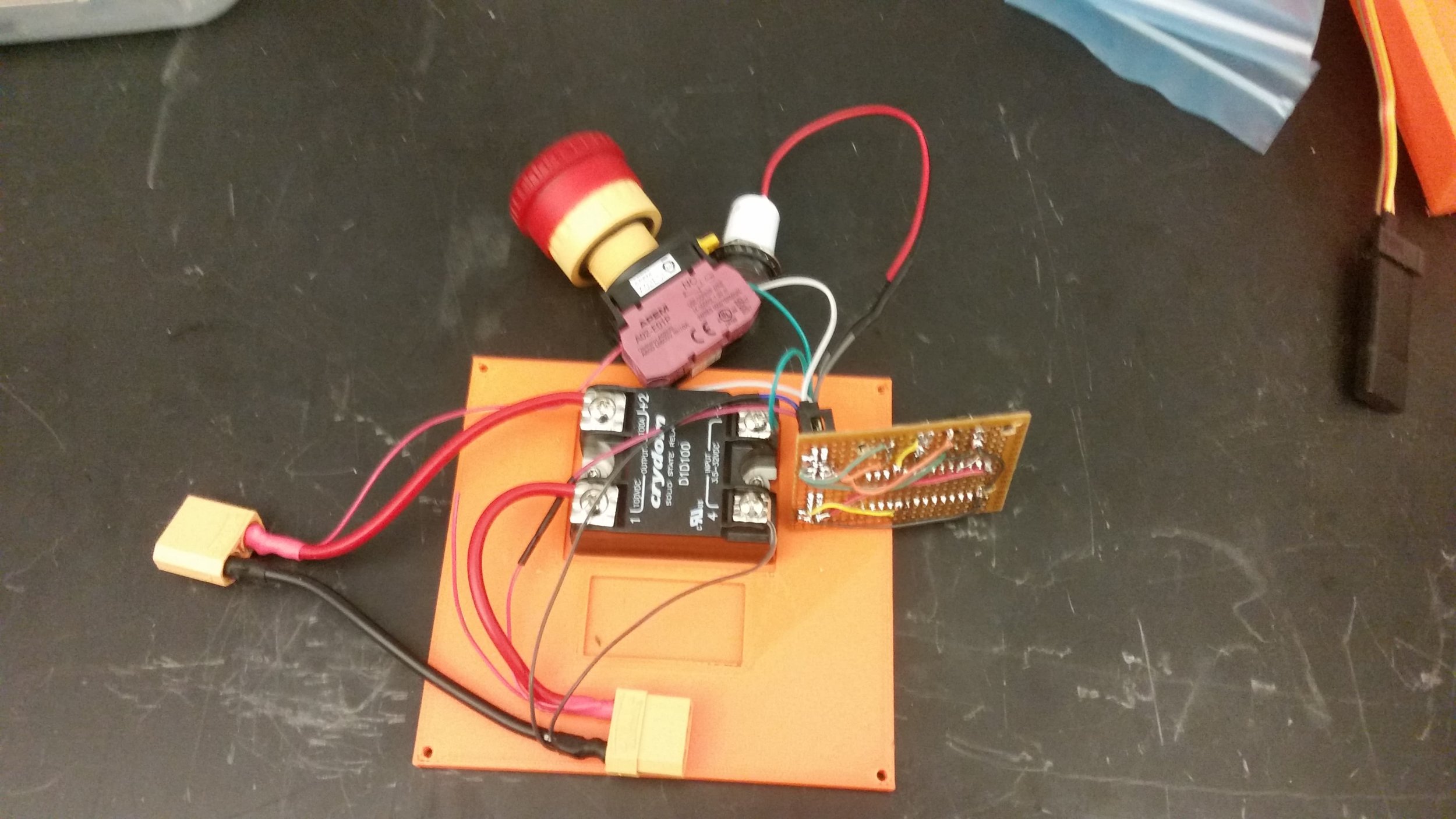
Each side of the robot shared a singe 4s battery and distribution board between the land and water mobility systems. The distribution boards feature a single XT60 input port on their lower (dry) side for power input. The current is then run through an automotive relay and out to the connector’s on the output side of the board. The automotive proved useful, because it allowed us to safe and power cycle the robot remotely without having to worry about plugging or unplugging anything. In addition to the drive systems, our other subsystems (ball handling and the pumps) were distributed between the other two boards wherever made the most sense from a wiring perspective.
For our second robot, we added another set of relays to automatically cycle the pump motors every 10 seconds. This really helped with priming, but was unfortunately not ready in time for the competition.
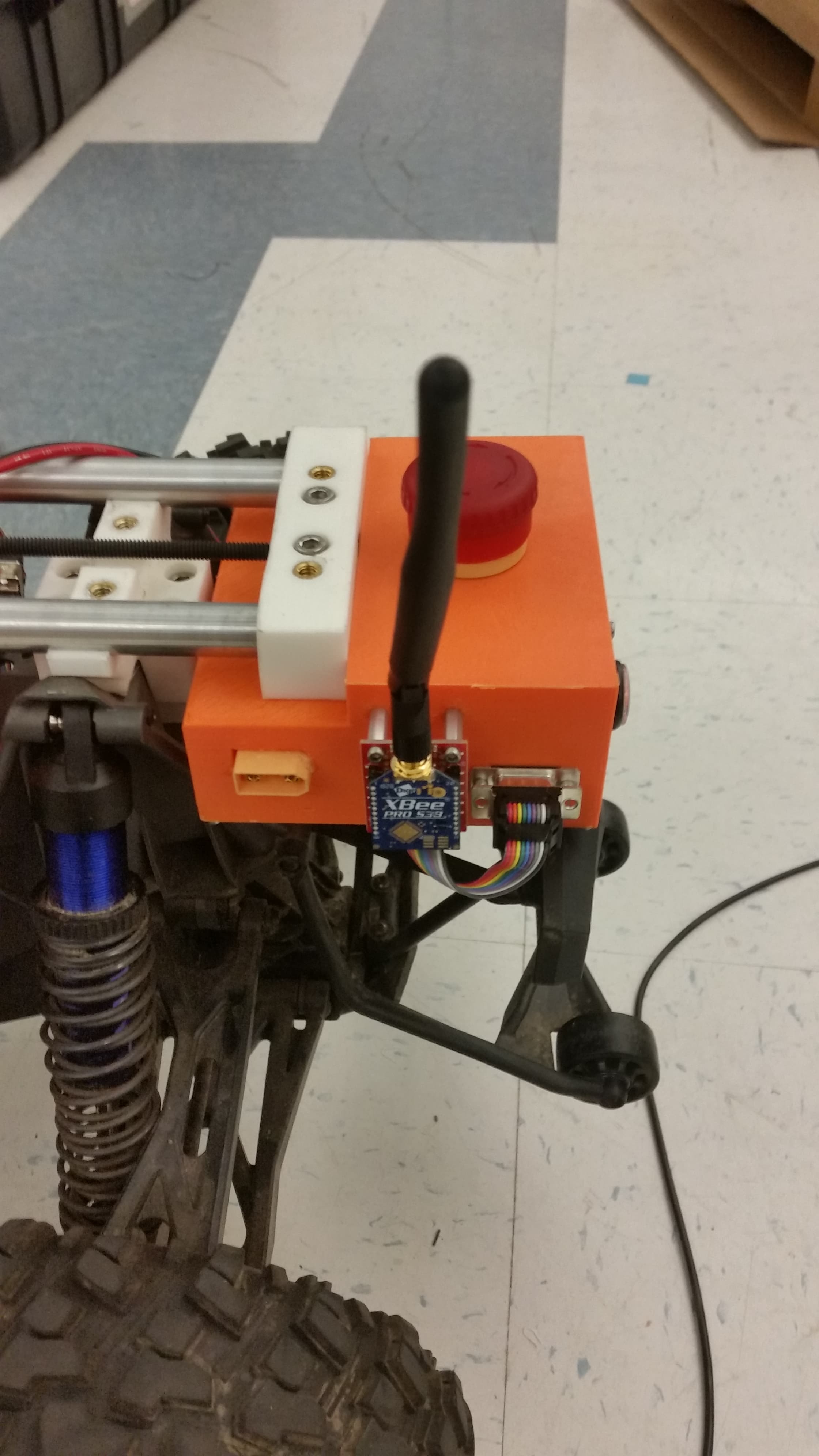
Control and radio:
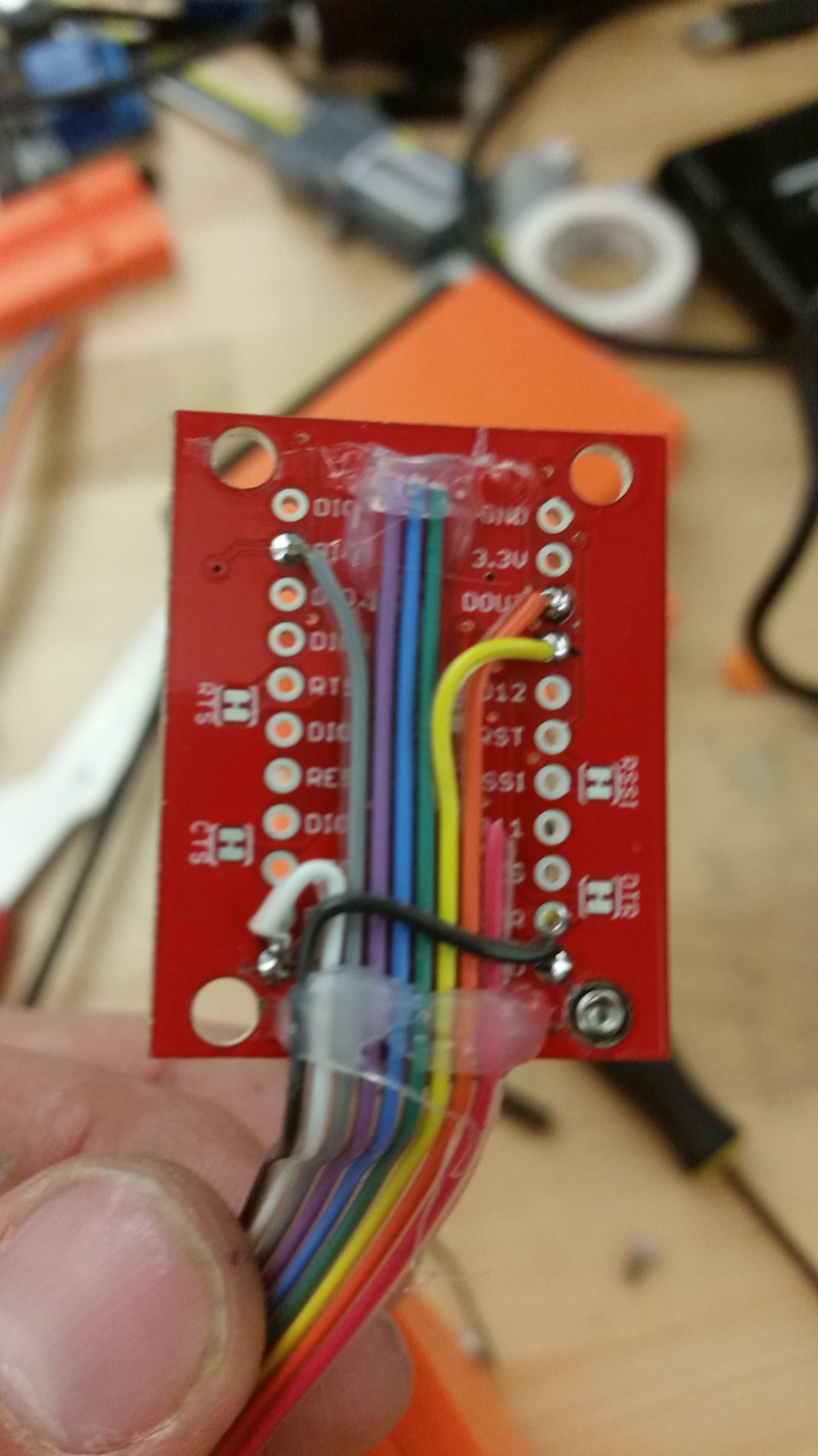
The RC receiver was housed inside the control cylinder along with the primary micro-controller (an arduino nano) and the power monitoring ESP8266. Command signals from the receiver were processed by the Nano, and then corresponding servo control signals were generated with a PCA9685 and sent out of the interface bulkhead. Several nano pins were also exposed directly through the bulkhead PCB to provide feedback, Serial, and general purpose I/O to the rest of the robot if needed (several of these were re-purposed to run pump priming control on the second robot).