The e-stop installed on Balto, with our test transponder in palace of DARPA's.
Overview:
One of the key requirements for any large (we count) robot competing in the DARPA challenge is a functioning estop system. When our original solution couldn’t be delivered on time, we decided to build our own. This is one of the rougher systems on the robot, mostly because it was built in so little time, but it works well, and is definitely nice to have. I plan to use a similar architecture (dropping Tier 2) on future robots even when it is not required.
Requirements:
For SUBT, DARPA requires that teams implement a 3-tiered E-stop system as follows. They also require that the robot give some indication that it is in an e-stopped state for tier 2 triggers. DARPA does not require that teams implement hardware E-Stops. However, for tier 3 that does seem prudent.
Tier 1: A wireless E-Stop controlled from the team’s base station.
Tier 2: A wireless E-Stop controlled by an XBee transponder mounted to the robot and controlled by DARPA.
Tier 3: A physical latching E-Stop (big red button).
For the first and second tiers, we will use a piece of code that inserts zero-motion commands to the twist mux node at a higher priority than ether the joystick or move-base. A Teensy (running similar firmware to steering) will be used to monitor the transponder for shutdown requests.
The system block diagram for Balto’s e-stop. The pullups are nice to have, but can mostly be ignored.
Balto with a tier 2 e-stop enabled. Note the Blue indicator led is lid.
documentation:
(versions as of 8/5/2019)
Tunnel competition rules [click me]
Transponder guide [click me]
Github: https://github.com/lellasone/Crawler (see firmware and crawler_control for relevant files).
Assembly:
This part of the project was completed on a very short time scale after our original solution fell through. It is a pretty rough build, and so I have left these notes pretty bare bones on the theory that (hopefully) I will be the only person needing to follow them. If that is not the case, and you are confused definitely feel free to reach out and I’d be more than happy to walk you through the process.
One item of particular note is the pin numbers. I frequently refer to pins according to a numbering scheme which is specific to the crawler project. It runs as follows: For all D-SUB connectors, pins are numbered such that looking at a female connector, with the short side facing up the first pin is in the lower left corner, and the second pin is in the upper left corner. For through-hole headers, the pins are numbered such that with the shroud gap facing down pin 1 is in the lower left hand corner of the header, and pin 2 is in the upper left hand corner of the header. I picked this numbering scheme because it means that adjacent wires in a ribbon cable increase and decrease by 1 relative to their neighbors. By convention, I have oriented the ribbon cable such that black is always pin 1 and red is always pin 9, the 10th pin on the rectangular headers is never used.
The CADs, firmware, and control software can all be found on the github. In addition to the 3d printed parts, the following components were used (along with ribbon cable and heavier gauge wire for power transmission.
(x1) XT90 Male.
(x1) XT90 Female.
(x1) estop button.
(x1) 100A SSR.
(x1) Indicator led.
(x1) Teensy 3.2
(x2) 817 Optocouplers.
Perf Board:
The first step in building the e-stop is to build up the perfboard with the Teensy and two optocouplers. The perfboard is by far the most fiddly part of the build, and I plan to replace it with a PCB when time exists. In the mean time, I have included fabircation suggestions and wiring notes below.
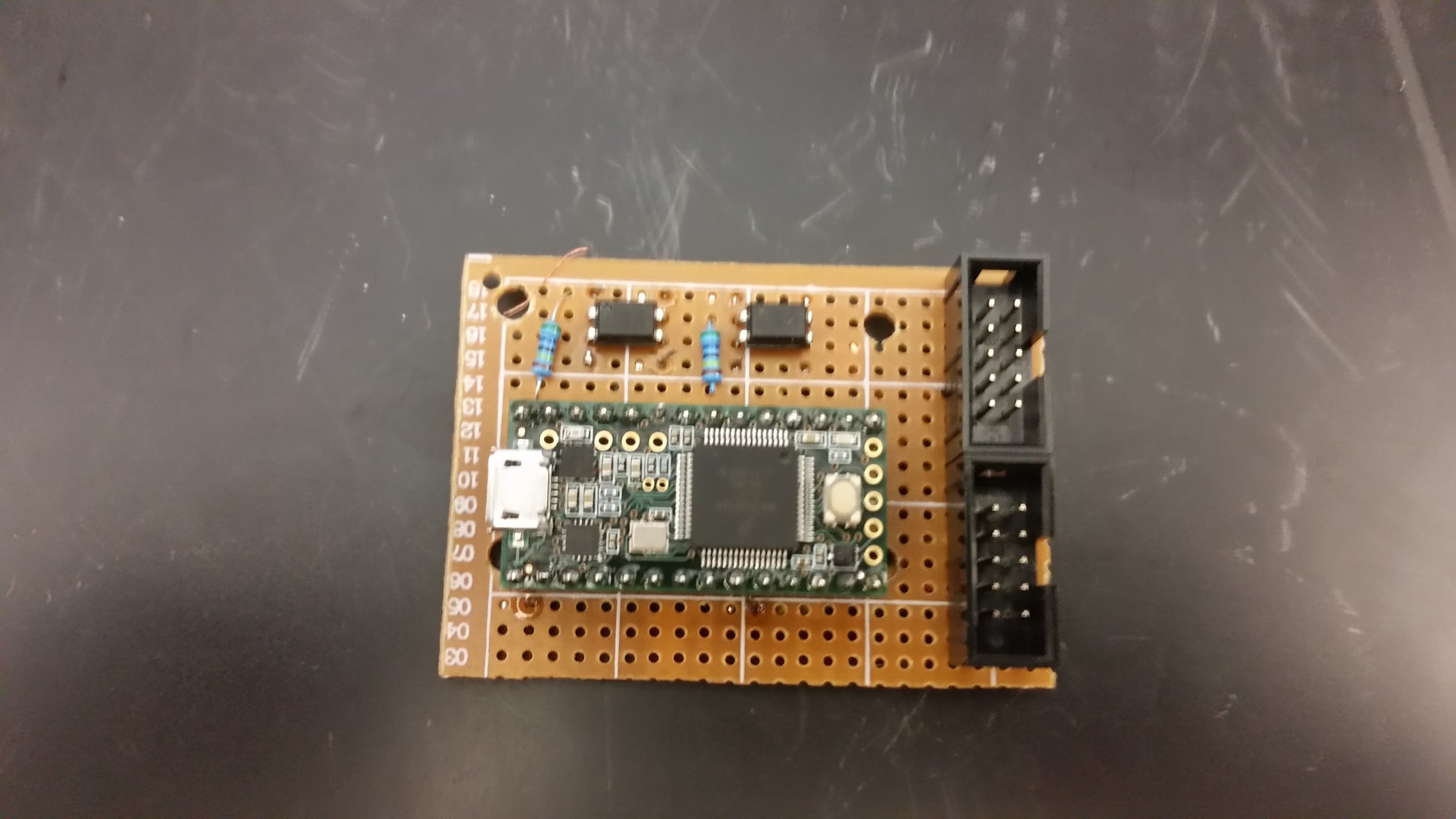
Begin by drilling and cutting a piece of perfboard to match the schematic in figure A. Once that is done, solder the Teensy headers (or Teensy itself, though I would advise against it), optocouplers, and shrouded headers, roughly as shown in figure C. Next, both optocoupler’s input cathode’s to Teensy ground, and the input anode’s to D16 and D23 (for led control and main power control respectively). Now, verify that the connections work by writing a test script to the Teensy (really, you want to catch these issues now before the rest of the wires go on), then connect the two shrouded headers according to the following tables.
Header 2:
This header connects the teensy to the D-Sub panel mount connector by way of a ribbon cable.
Pin 1 - Optocoupler High Side (D23 controlled)
Pin 2 - Optocoupler low side (D23 controlled)
Pin 3 - Optocoupler high side (D16 controlled)
Pin 4 - Optocoupler low side (D16 controlled)
Pin 5 - Short to pins 6 and 8
Pin 6 - Short to pins 5 and 8
Pin 7 - Short to pin 3
Pin 8 -Short to pins 6 and 5
Header 1:
This header connects the teensy to the D-Sub panel mount connector by way of a ribbon cable.
Pin 1 - Teensy Ground
Pin 2 - Teensy 5v
Pin 3 - Teensy D8
Pin 7 - Teensy D10
Pin 8 - Teensy D9
Figure A: Cut down the perf board to match these dimensions and holes. When in doubt it is better to be slightly too small than too large, as you won’t be lacking for board space.
Figure C: The pulldown resistors in this photo are optional, and I would suggest leaving them off.
Figure B: The underside of the board, presented here with some horror. Note that the high-side input for the main power optocoupler is provided by a resistor. (In my defense, we were very short on time and I did clean it up more before install)
Figure D: Place the reference corner of the board in the forward/top corner of the housing wall.
Wiring:
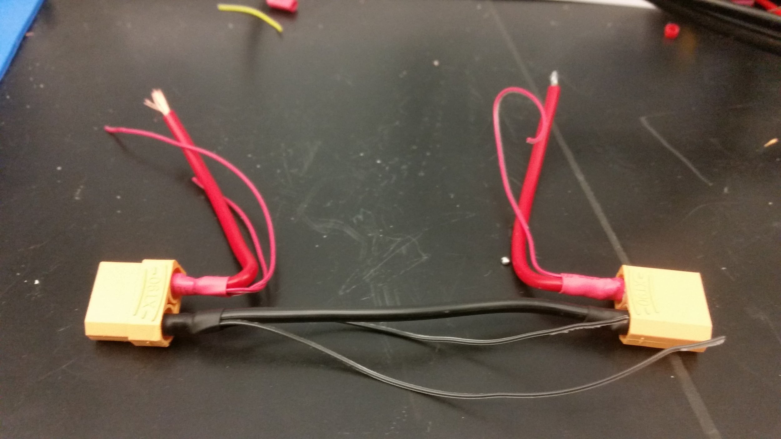
Figure E: Power wiring harness, the ground wire should be sized to fit across the estop housing. The vcc wires should start out around 6in in length and can be cut down to ease assembly once the other wiring is completed.
Once the perfboard is completed, begin the wiring process. First, create the power wiring harness as shown in Figure E (Note that it is easier to make the VCC wires shorter than longer), and test that it fits across the housing. You will want to use no less than 14 gauge wiring, and 12 would be better if available. Note the secondary wires, which will be used to run power to the switching system and indicator led.
With the power harness completed, the next step is to begin routing each component. The list below outlines how each component is connected to the others. Unless otherwise noted, all connections can be made with 26 gauge wire. For connections running to crimp terminals use solder balls or crimp-on ring terminals. For connections running to the perf board use single location femail pin headers.
All of the components connect to the second pin header except the ribbon cable.
Connections by component:
Estop switch block - One terminal connects to VCC IN, the other connects to the perf board (pin 2).
Estop led block - One terminal connects to perfboard pin 7, the other connects to perfboard pin 8.
Indicator led - One pin connects to perfboard pin 4, the other connects to perfboard pin 8.
VCC IN - Connects to the SSR high side (12 gauge wire), Estop switch block.
VCC OUT - Connects to the SSR low side (12 gauge wire), perfboard pin 3.
SSR - Switch H: pin 1, Switch L: battery ground, Controlled H: VCC IN, Controlled L: VCC OUT.
A not-quite-final test fitup of the wiring. I strongly recommend making the leads as long as possible even if it makes assembly slightly trickier.
Connections by pin (header 2):
Pin 1 - SSR control high side.
Pin 2 - Estop switch terminal block.
Pin 3 - VCC OUT (XT90 output).
Pin 4 - Indicator led(either lead).
Pin 5 - Battery GND.
Pin 6 - Indicator led(either lead).
Pin 7 - Estop led terminal block (either terminal).
Pin 8 - Estop led terminal block (either terminal).
The panel mount connector should be outfitted with a ribbon cable long enough to reach the perfboard, connected such that pin 1 on header 1 connects to pin 1 of the D-Sub connector. With the wiring complete you can now install the SSR onto the bottom plate, and the E-stop, indicator led, perf board, and panel mount connectors into the housing.
Transponder:
After you have assembled the e-stop housing, and tested that all of the components work, the final step is to wire up the transponder carrier board. Connect a male D-Sub connector to a length of ribbon cable, and then solder the ribbon cable in place according to the following table. Note that pins are given according to their female counterpart (and incidentally their corresponding perfboard pin). Once you have installed the transponder and verified that it works, consider using epoxy or CA glue to strain-relieve the solder joints.
Pin 1 - GND
Pin 2 - 5V
Pin 3 - DIO1
Pin 7 - DIN
Pin 8 - DOUT


