
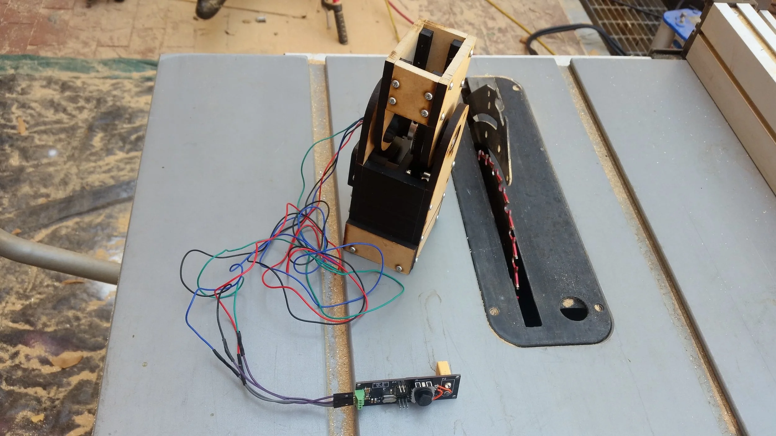
Version 1.0 of the controller. I did need to make one minor rework on the joystick inputs, but other than that it worked perfectly. The green header connects to the motor, the 6 pin header is for programming, the 2 pin header is for debug, and the orange XT60 connector on the back provides power. (These pictures were taken before cleaning the flux)
Summary:
This is a generic stepper driver motor tester that should work with a range of NEMA 11, and NEMA 17 motors. Moving the joystick forward and backward allows for a range of step rates in both directions, and flicking the joystick right or left allows the user to select from between 1/2 and 1/32 microstepping. The MCU is an 328p flashed with an Arduino Nano bootloader, and the stepper driver is a DRV8825.
This was a pretty simple project, so I have elected not to include a build log. The gerber files, Altium project, and arduino files can be found below along with instructions for adding your own logo, and my suggested improvements for the second revision.


Improvements:
I don’t expect to make a second rev of this project any time soon, but if I did I would suggest the following modifications:
Consider switching to a Trinamic or generally better quality driver.
Run the driver feedback lines to LEDs rather than IO pins.
Provide user-accessible current configurations.
Snap-lock connectors would be better for the stepper wires.
Logo:
This is my first PCB to bear my makers mark! Adding a makers mark to my PCBs has been a goal for a while, but I haven’t been able to justify the time on previous boards. Turns out the process is pretty simple:
Get a DXF of the logo. I explored from the wax stamp CAD, but there are lots of ways to do this.
(Optional) Clean up the file in Inkscape to get exactly what you want. It’s easier to edit here than it will be in Altium.
Using “File -> Import -> DXF/DWG” enter the import wizard. I used the following settings with some success:
1 AutoCAD unit: 200mil
Default Line Width: .1mm
Layer_1 : Top Overlay (this is likely specific to my file / Inkscape)