Overview:

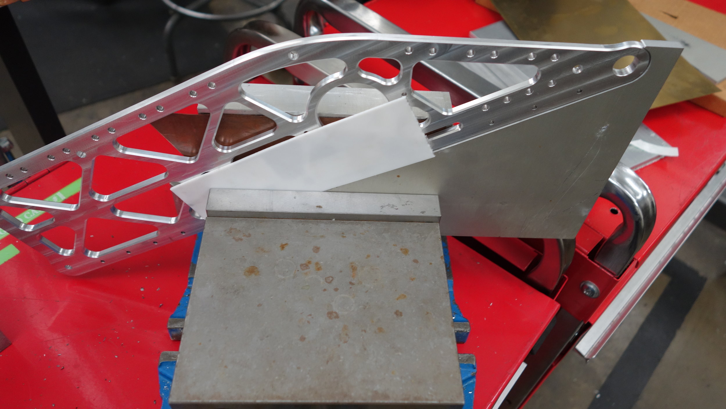
The right rib partially assembled.
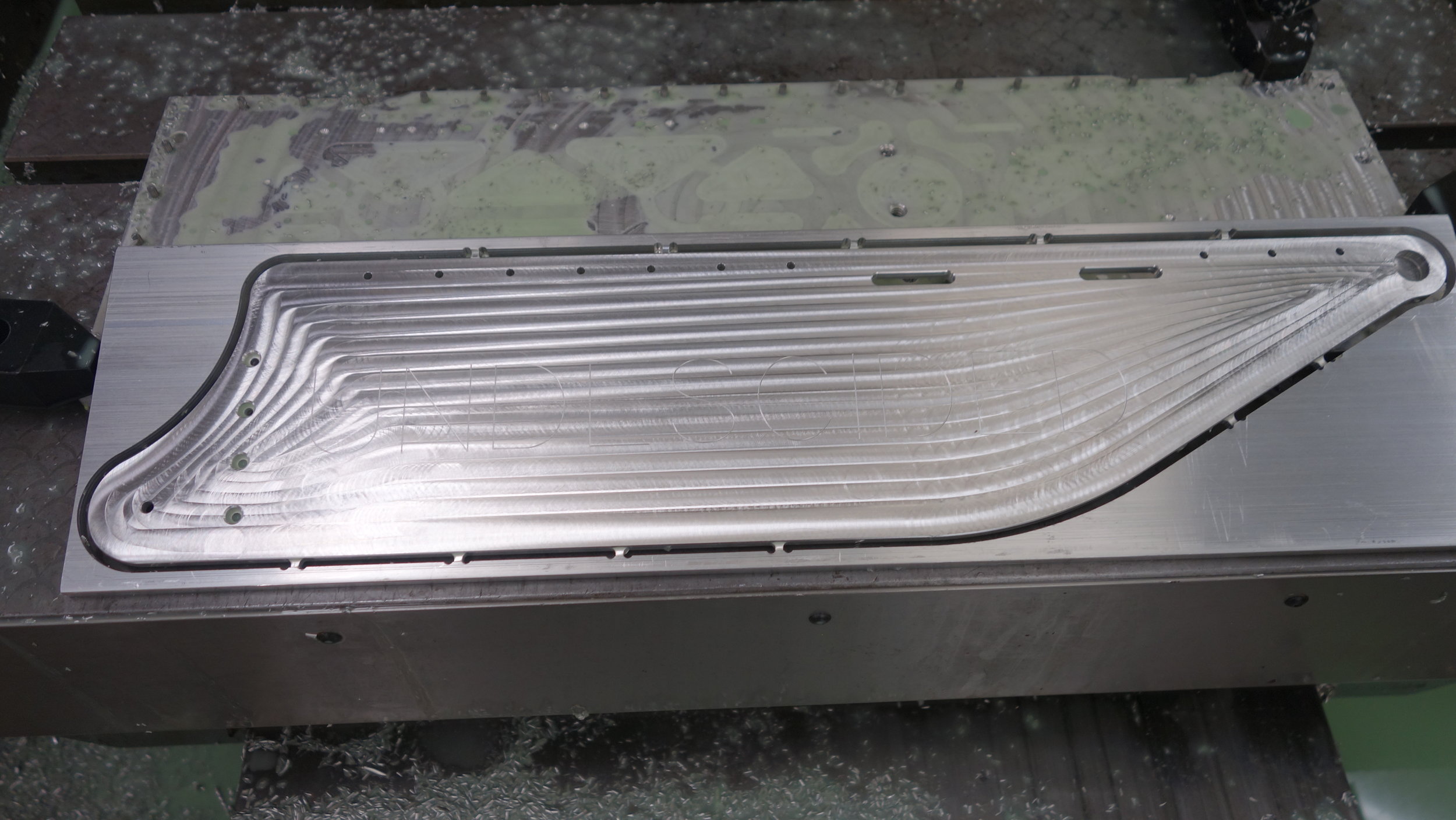
This post outlines the fabrication process for our side panels, which run the length of the ship and provide mounting geometry for most of our land mobility systems. The side panels are made from 6061-T6 aluminum, and all four were cut on one of the school’s VMCs using our fixture plate from earlier in term.
Making the side panels was easily the most time consuming portion of our fabrication process for Frog A, requiring over 70 hours of reserved CNC time. With that said, the majority of that time was spent checking cuts, tweaking setups, and repairing/replacing errors in prior runs. All told the 4 plates only have around 8 hours of actual “cut time” so I am hopeful that we will be able to reduce fabrication times substantially moving forward.

All four of the side panels prior to assembly.

The right rib, post assembly.
Cutting the Faces:

The fixture plate and prepared blank on our Fadal VMC15 before the first operation.
Setup:
Each side panel was cut out of a 19.5” by 5” by 0.25” blank of extruded aluminum bar stock. The stock was purchased from online metals in 6’ lengths (to reduce shipping costs) and then cut to rough size on the shop’s horizontal bandsaw. One 5in edge edge was then finished on a manual mill to provide the two reference corners for the part. The part edges were then deburred on a Scotchbrite wheel, and the two reference corners were marked with Sharpy.
Tabs helped increase process reliability and came off easily using the bandsaw.
Fixture:
We set the work coordinates for this part to be the top rear left corner for the first operation, and the top front left corner for the second operation, with the part about it’s long axis. This meant that we were using the same physical corner as our zero for both faces, thus eliminating the risk of errors due to irregularly sized stock. The tools were measured from the center of the workpiece using the shop’s 4in height guage*. In some cases it was necessary to lengthen the tools slightly to ensure that they were able to reach the bottom of the parts given our short fixture plate. We also found that some of the operations raised burrs on the non-part portions of the stock. We solved this by sanding them down, but I think moving to facing the entire top of each part would be a good idea for round two.
The blanks were held using our 5in fixture plate, and tensioned with 1/4-20 miteebites, spaced with some copper shims as needed to accommodate thickness variations in the stock. This seemed to work well, and I would certainly re-use a similar fixture for future panels and flat parts in general. We did find that with the thin (1/8in) edges on some of our parts it was necessary to add tabs since the foil tended to tear when thin enough to be convenient. Tabs about 1/8in wide and 40-50 thou high seemed to be more than sufficient, though we did use several on the longer faces of the panels. These seemed to cut better than fewer larger tabs.
*Note Post Build: Our fixturing setup for round two was vastly better, I would suggest copying that if you plan to cut parts like this in the future.
Faces:
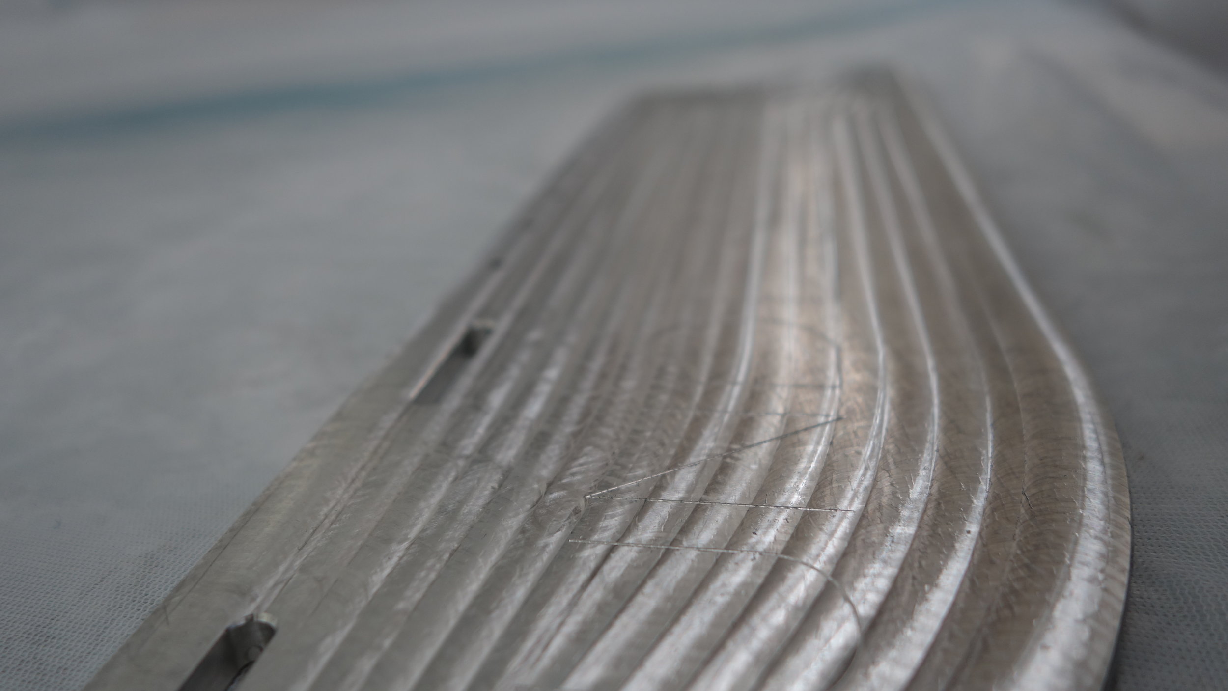
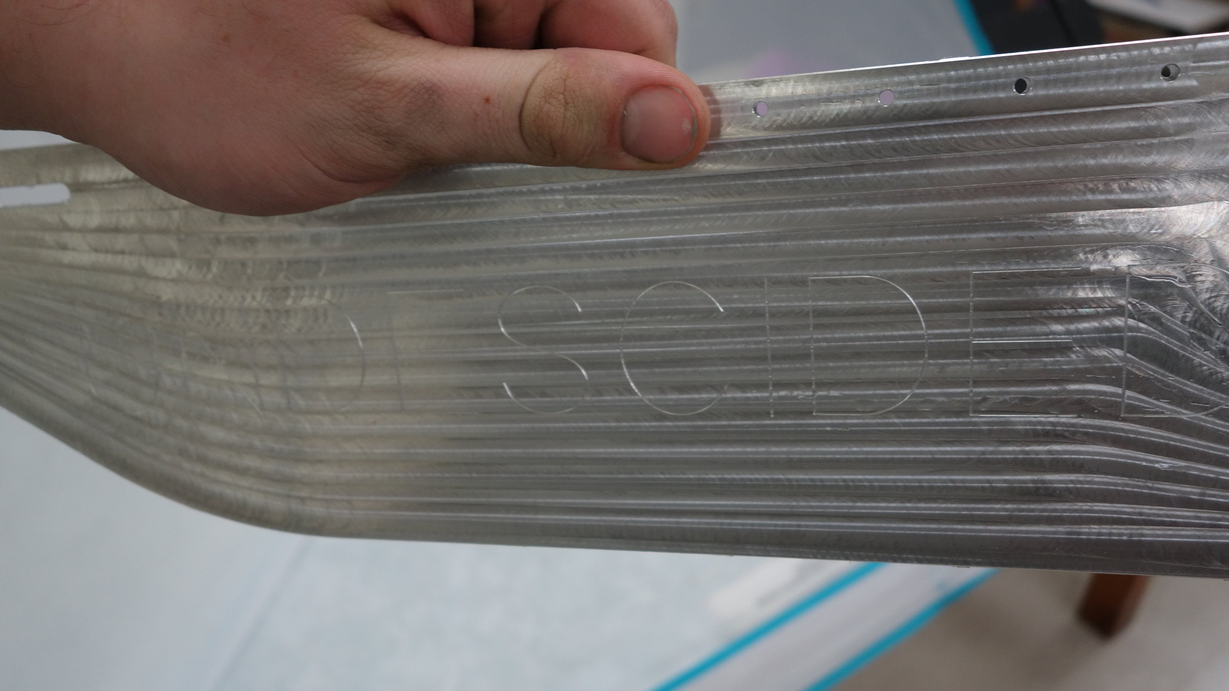
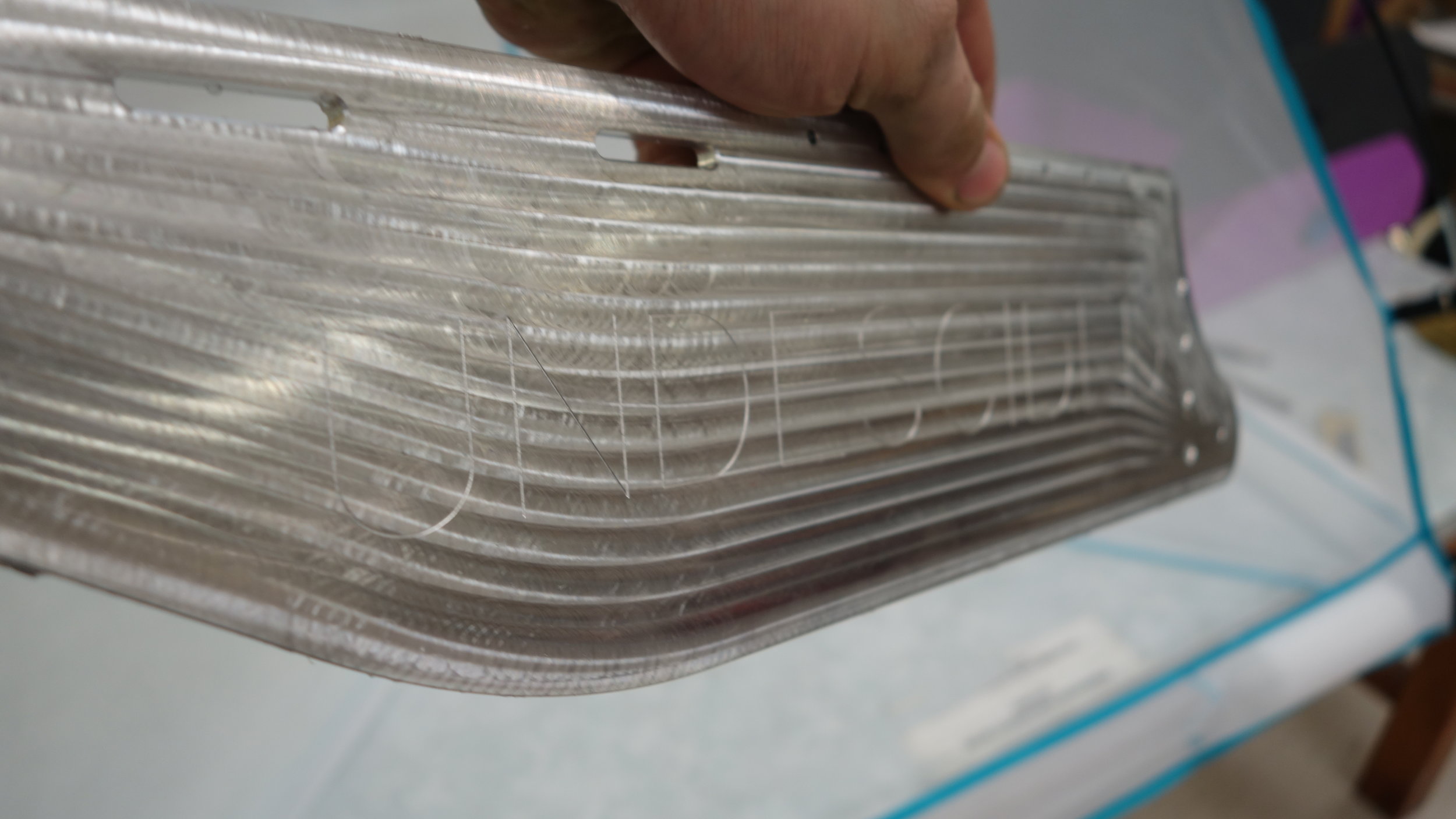
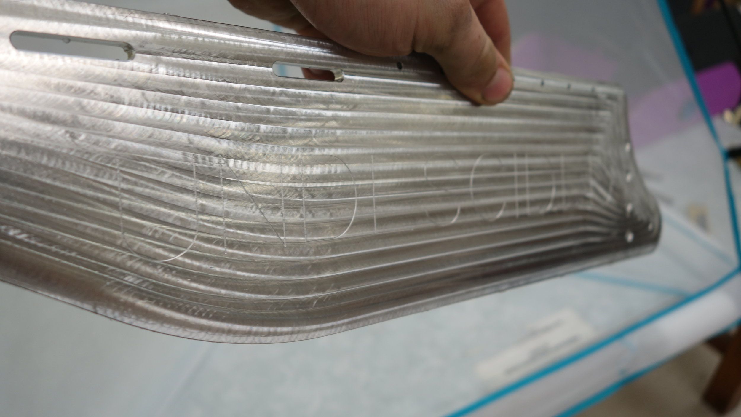
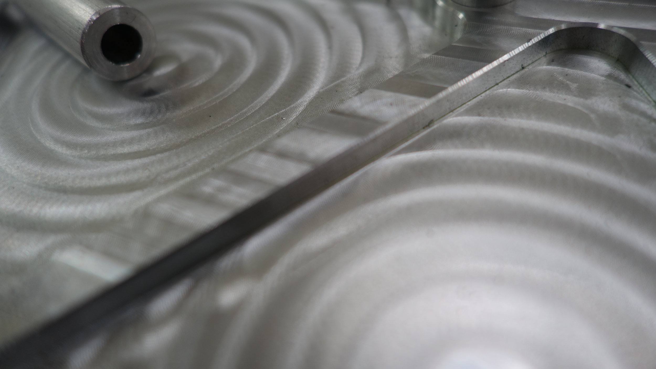
The first operation on all of the parts was to face the simpler side (inner for inner ribs, outer for outer ribs). With a slightly dull HSS endmill machining marks are inevitable (though they are less pronounced in person than in the images below). To make the best of things, I decided to use a contoured spiral to cut the outer faces. This added about 10 minutes to each outer plate, but left us with a cool pattern vaguely reminiscent of a wale. That said, it did make it a bit hard to read the engraved “Undescided” (our team name, yes that is the correct spelling) on the outside of the panels though so I plan to move to fly cutting for the next batch.
On a more practical note, the facing operations did a good job of underlining just how warped our stock is. For most of the parts we ended up having to take multiple passes to the tune of 15thou per side in order to get a clean surface. It is not clear to me exactly how much of this has to do with our fixturing/cutting methods and how much has to do with the actual stock, but it is concerning in any case.
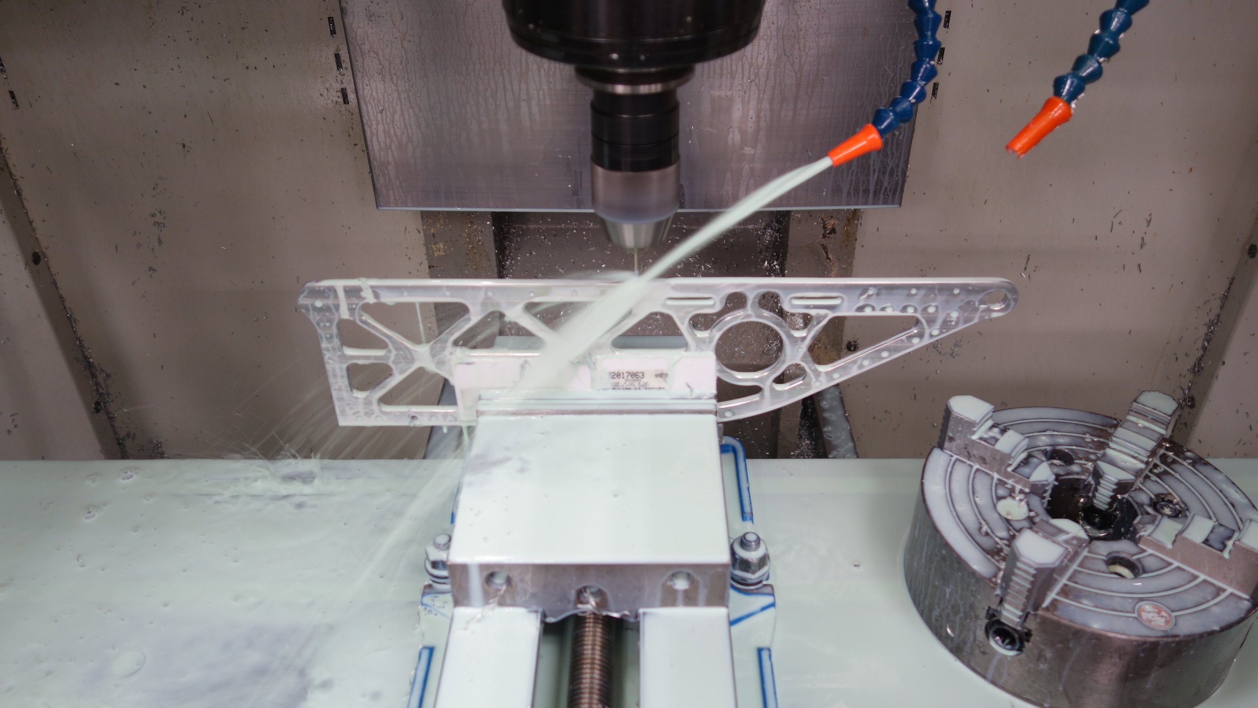
Lightening Pockets:
Both the inner and outer panels had significant lightening pockets cut out to reduce the part weight. The inner panels had through-cut lightening holes, while the outer pockets were cut with our rough approximation of an issogrid. Removing as much material as we did proved very time consuming. The inner panels took around 45 extra minutes to cut, while the outer ones gained around 75 extra minutes. That said, we ended up being quite tight on our weight budget, so the extra fabrication time was more than worth it.
The pockets were first roughed using a 1/4in endmill, and then finished using a 1/8 in endmill to get into the smaller pockets and tighter corners. We used a conventional 2D pocketing strategy for both passes, and then cleaned up the walls with a 10 thou finishing pass. These cuts would likely have benefited from an adaptive approach, but the FADAL lacks the requisite block processing, so we stuck with simpler machining strategies.
These cuts are one of the parts of our process I am least happy with. Although the pockets turned out well in the end, we got a lot of chatter and resonance in the part while cutting. I suspect this was due to a combination of HSS tooling and long tool stickouts. I plan to use much more conservative stickouts, as well as carbide endmills, for the next set of plates.
Note: The weight budget ended up being tighter than we expected. With that in mind, the inner panel lightening holes were sufficient, but the outer panel pockets were not. I plan to remove significantly more material from the next set of plates.


Tapped Holes:
Tapping the top holes, all of the CNC work for the edge tapping was done on the TM1.

Manually tapping some of the 6-32 side holes.
4-40:

Not a setup I am exactly proud of… it did work though.

A tapped lower standoff hole. These provided the spacing and structure for the ribs
One of the more interesting parts of this design, were the vertical mounting holes. The top and bottom edges of each panel have a number of tapped 4-40 holes used to connect the plates to the hull-bottom, and hopefully used to connect the ball hardware to the plates. With several hundred holes to drill, we decided to approach them as a CNC operation, and successfully roll-tapped all of the holes using the Haas TM1. Since the first set of plates varies in thickness by 15 thou, we found it necessary to keep track of which edges were “reference edges” so that we could drill and tap the the holes relative to those edges. This required a large number of fixtures. We plan to use custom soft jaws for the next batch.
The other set of 4-40 holes found on the robot were are the standoff mounting holes. These are used to connect the inner and outer panels of each rib, and are tapped about 100 thou deep. Since we do not have a bottoming roll-tap, we chose to tap only the first turn of the threads and then chase the rest out using a 4-40 screw. This worked well and will be replicated on future builds.
6-32:
In addition to the 4-40 screws used to tension our standoffs, we also have a number of 6-32 tapped holes used for mounting the gearbox assembly’s as well as the ball handling systems (possibly). Since these interfaces had not been finalized when we began fabrication, the holes were drilled as 4-40 clearance holes and then finished by hand during assembly.
10-24:
There is a single 10-24 screw used as a shaft for the lower, rear, belt rollers. It was drilled to size on the CNC and then tapped manually at the tapping station.
An angle block for drilling the bow holes.
Test fit-up of the jig for our bow holes.

Teflon strips were used to prevent scratches.
Chamfers:
We used three sizes of chamfe on the side panels. see below for a summary of each. The pocket and perimeter chamfers were cut with a 1/4in, 4 flute, spiral, carbide chamfer mill, and the hole chamfers were introduced with the 5/16 HSS spot drill during the initial spotting operation. All chamfers were 90 degree.

Drilled holes on the part were all furnished with a 10 thou spot-drilled chamfer. That seemed to work well, and I would use it again. The milled pockets (lower) were milled with a 1/4in carbide endmill and given no chamfer.
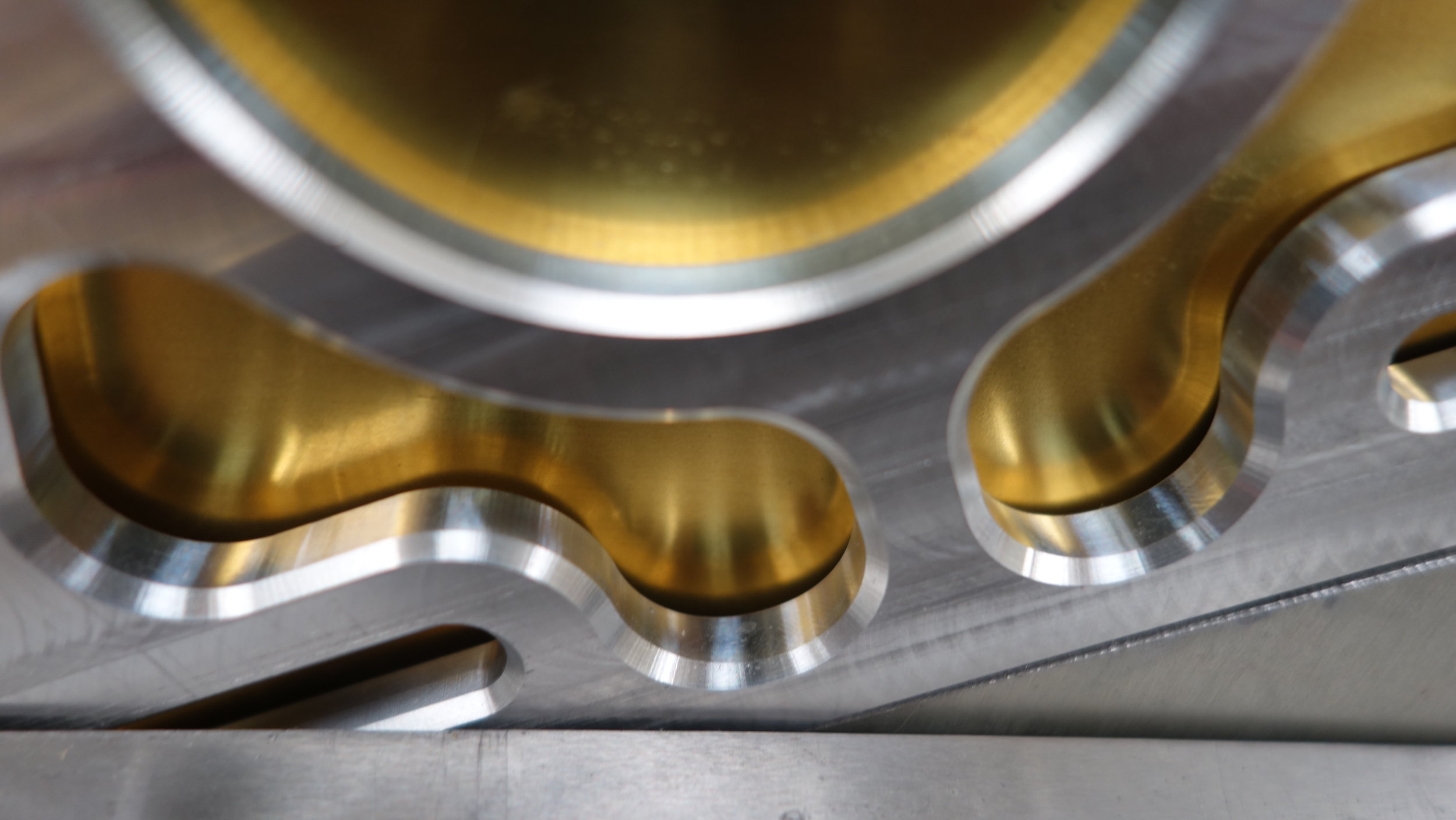
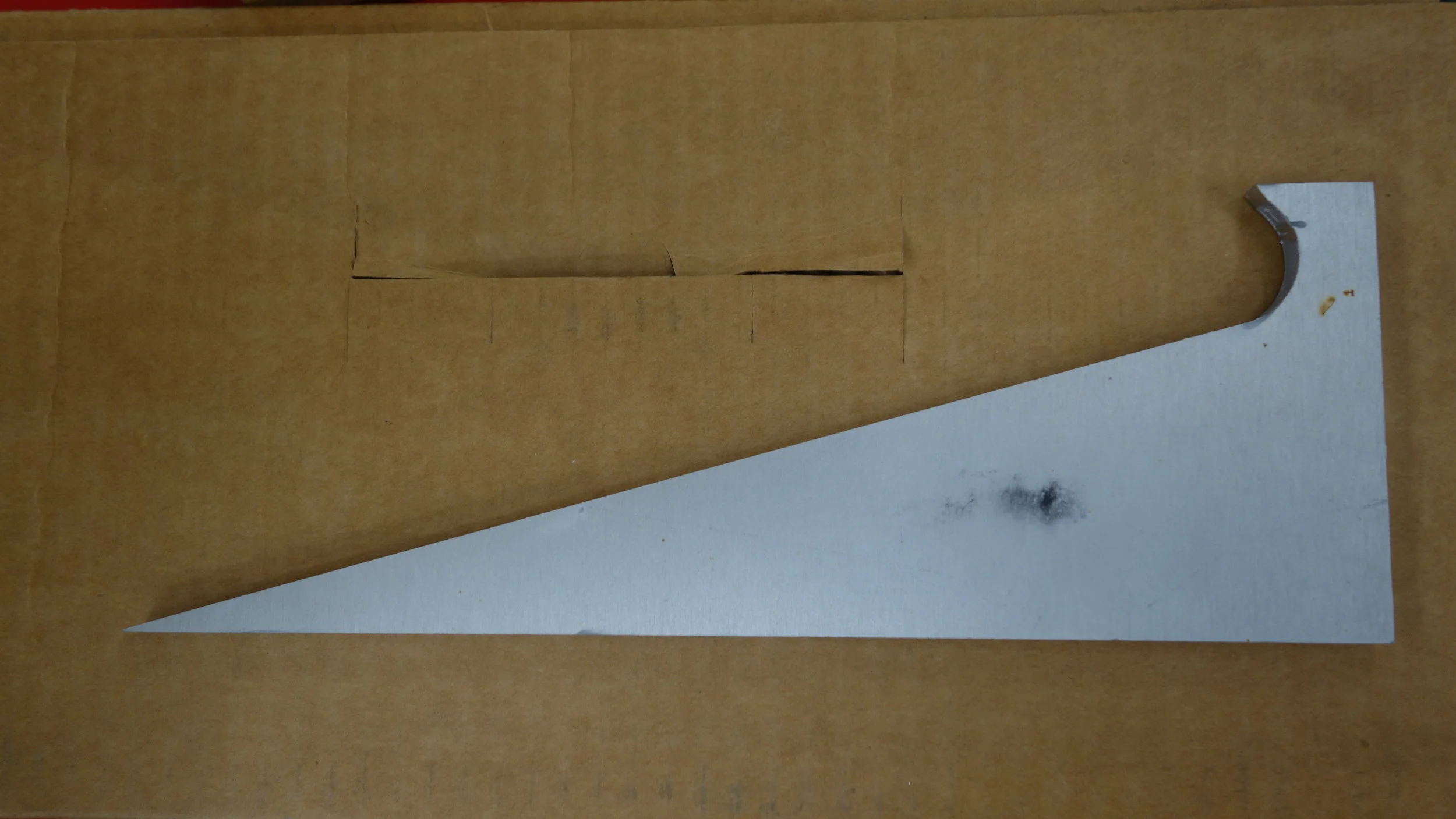
The test-part was given a 40 thou chamfer on both sides. This was by far our prettiest option, but ended up cutting into the available edge space a bit too much.

The 4 production parts were given a 15 thou chamfer on all edges. This worked well and looked good. Although, as you can see, we did get some chatter towards the inside of the part.


