
The left outer panel shortly after machining, but before the bronze bushings had been pressed.
Our second round of hull panels was largely the same as our first round. In part because we were satisfied with our first robot’s performance, and in part because we wanted to maintain parts compatibility between robots. With that said, there were a few substantial improvements to the design and fabrication process. In articular, we expanded our use of issogrids to substantially reduce part weight (without reducing part stiffness), switched to fly cutter surfacing, and made a few process tweaks to improve overall stiffness.
Overall I am very pleased with our second round of panel fabrication. We were able to cut the parts to tighter tolerances, with no scrapped parts, in about half the time.

IsoGrid:
One of the big focuses for the second generation panels was weight savings. In order to accomplish this, we replaced the previous (much wider) pocketing pattern with a true issogrid. This reduced the weight from 1.25'lbs to .8lbs, and brings the outer panels to just under 50% volumetric metal removal.
We cut the iso-grid in two stages. First, the triangles were all roughed using a 1/4in endmill. This removed the majority of the material. Then the corners, and some of the smaller pockets, were finished using a 1/8in endmill. Both operations used HSMworks 3D adaptive operation with no stock to leave. The second operation was configured for rest machining and also removed the 20thou radial stock to leave from the first operation. Each operation took about 1:20 with fairly conservative feeds and speeds.
One very substantial time saving for this round of panels was the switch to all carbide tooling. For the 1/8in endmill that meant a nearly 6x increase in volumetric metal removal over the HSS endmill we used for our first round of panels.
Although the operations themselves were fairly time-comparable to the larger weight reduction pockets from our first robot, I should note that the CAM was significantly more time intensive. In particular, selecting all of the faces to be cut caused significant slowdowns and periodic crashes in Solidworks.
Cutting the iso-grid did not seem to increase warping. If anything it may have contributed to a reduction in warping relative to our much larger lightning panels from the first round of plates.
Overall I will certainly re-use the pattern when weight budgets are tight.

Surface Finishs:
Thoughts:
For this round of outer plates, we decided to experiment with fly cutting rather than using the 1/2in endmill for facing. Overall I am very pleased with the results. Both the inner and outer faces seem cleaner, and the shinier surface really makes the engraving pop (see image below). Cycle times were also reduced by around 70%, even using multiple passes.
We got some smearing with all of the recipes we used (see results right), but even so I like the results well enough to use the superfly for future projects. Of the recipes we tried, I think 5 was the best overall.
For the inner panels, which were faced with the same 1/2in endmill we used on robot A, we decided to try a brushed look. The parts were cut exactly the same way as last time, but were then run over a medium Scotchbrite pad. The results were definitely not as shiny as an unmodified machined surface, but I think the look was a bit cleaner overall. The brushed look did seem to hide subsequent scratches slightly better than the flycut surface we used for the outer panels.
Experimental Results
All cuts taken with a 2.5in Tormach SuperFly, with a 2” stepover, running 2500RPM and 30IPM.
7 thou, 3 thou, engrave.
Looked good, slight smereing, crisp lines, raised a small bur.
7 thou, 3 though, engrave, .5 thou
Looked good, slight smearing, crisp lines, no burr.
7 thou, 3 tthou, engrave, 0 thou
Looked okay, significant smearing, no burr.
10 thou, engrave, -.5 thou
Looked Poor, significant smearing, smeared lines, some burr.
10 thou, engrave, .5 thou
Looked Great, minimal smearing, no burr.

The robot’s outer surface after fly cutting and engraving. I think this combination really pops well, and will certainly re-use it where visual is a top priority. One thing to note is the sharp vertical lines between passes. Those were reduced on the Fadal (which is better trammed), but still suggest that running passes long-wise might be better for future parts.

The right inner panel after machining and “brushing”. The machining marks are still clearly visible, but I think the effect is a bit more subtle than a straight machined surface.
Tolerance Improvements:
Surface Flatness:
Our last round of hole panels was plagued by flatness issues (on some parts we were out by as much as 15 thou). For this round we made a few critical changes. First, we re-designed the surface plate to allow for machining the entire top surface of each blank. This allowed us to fully remove the skin from each part which seems to have helped reduce twist by around 60%. Second, we planned in 0.030in of surfacing. This gave us considerably more wiggle-room for facing both sides flat.
Our results were still not perfect, but we held to our 5 thou flatness and thickness tolerances on all 5 panels (3 thou on thickness, and 5 on flatness, measuring with a height gauge on the surface plate). For the most parts the solutions we implemented were things we knew about before starting the first batch, so I think the lesson here might be that it pays to start off with a better process when possible.
Hole Tolerances:
Not really a full investigation of boring as an alternative to drilling. Did some inspection with gauge pins just to see what we are getting, and I’m going to leave the results below for future reference.
Counterbores - Rated: .2188 Actual: .221-.222, Variance: Minimal
Rear pulley hole - Rated: .1590, Actual: .160 - .161, Variance: N/A

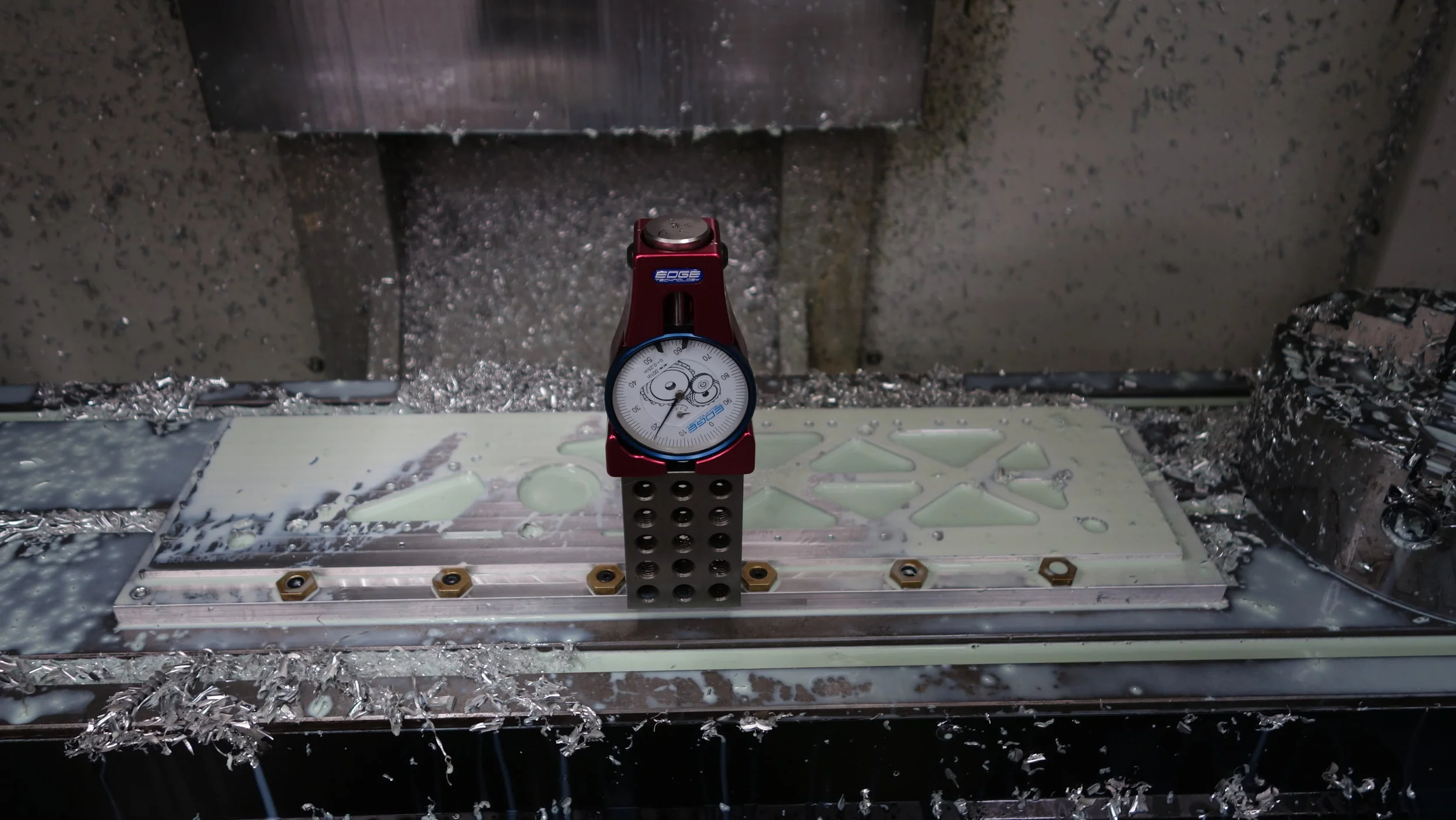
Getting a vertical dial indicator really helped improve our process for surfacing the parts.

Being able to “see” the thickness variations and bowing made it much easier to decide where to spend our extra material.

Fabrication Pictures:

Taking a shot at chamfering both sides without a relief cut. This had the unexpected effect of actually raising a larger burr than would otherwise have been present. Not a great idea as-implemented but maybe an area for further experimentation.

Sometimes you need a tool extender… Sometimes the best tool extender in the shop is a TTS collet holder… It worked?

The Haas’s tramming error is particularly notable during facing operations. In practice we did not find the ridges compromised water-sealing so it was largely a non-issue.
As zeroing setups go I can’t say this is my favorite, but the 1-2-3 block is only out by a few tenths, and it did work well.

The ME shop’s vertical bandsaw was down so we used the student shop’s instead.

A blank after being cut and milled to size. The sharply definitely helped cut down on fixturing errors.