Summary:
Greetings! This is my build log for the main body of the belt grinder. During this phase of the process, my goal is to complete fabrication of the main structural plates, and then to assemble a mockup of the grinder body. This will let me get a sense for the machine’s ergonomics before setting up the electronics and finalizing the platen design. At this point the grinder is installed and the pivots all work. Next up will be fabricating the platen assembly, and installing the electronics. Until the grinder is up and running we won’t really know how it works, but for now I am very pleased. All of the moving parts turn smoothly, with minimal slop, and the overall structure seems solid. The hold-down lever in particular works quite well (credit to Reeder Grinders for that idea).
I have organized this build log (and pictures) by machine used, rather than part created, since that best matches my actual process for this project. It is also worth noting that both the handle, and tracking plate are completed in these pictures. However, I’ll include their build logs later.
Assembly:

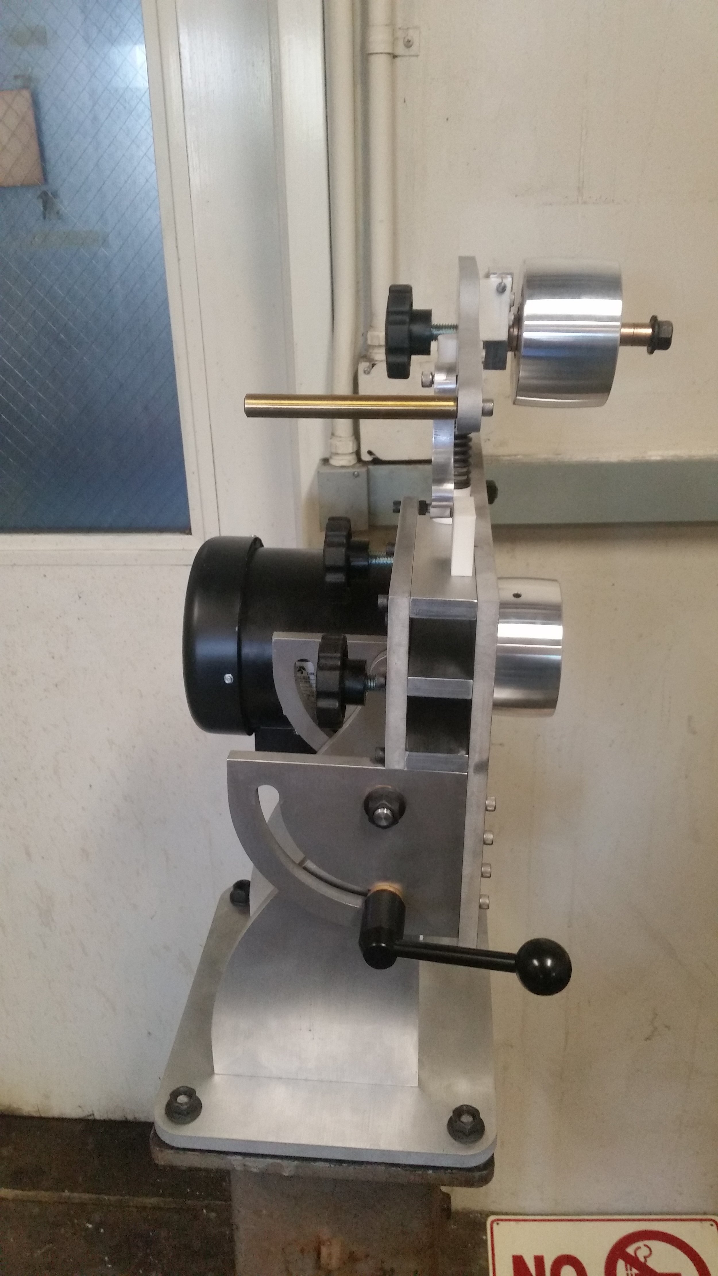
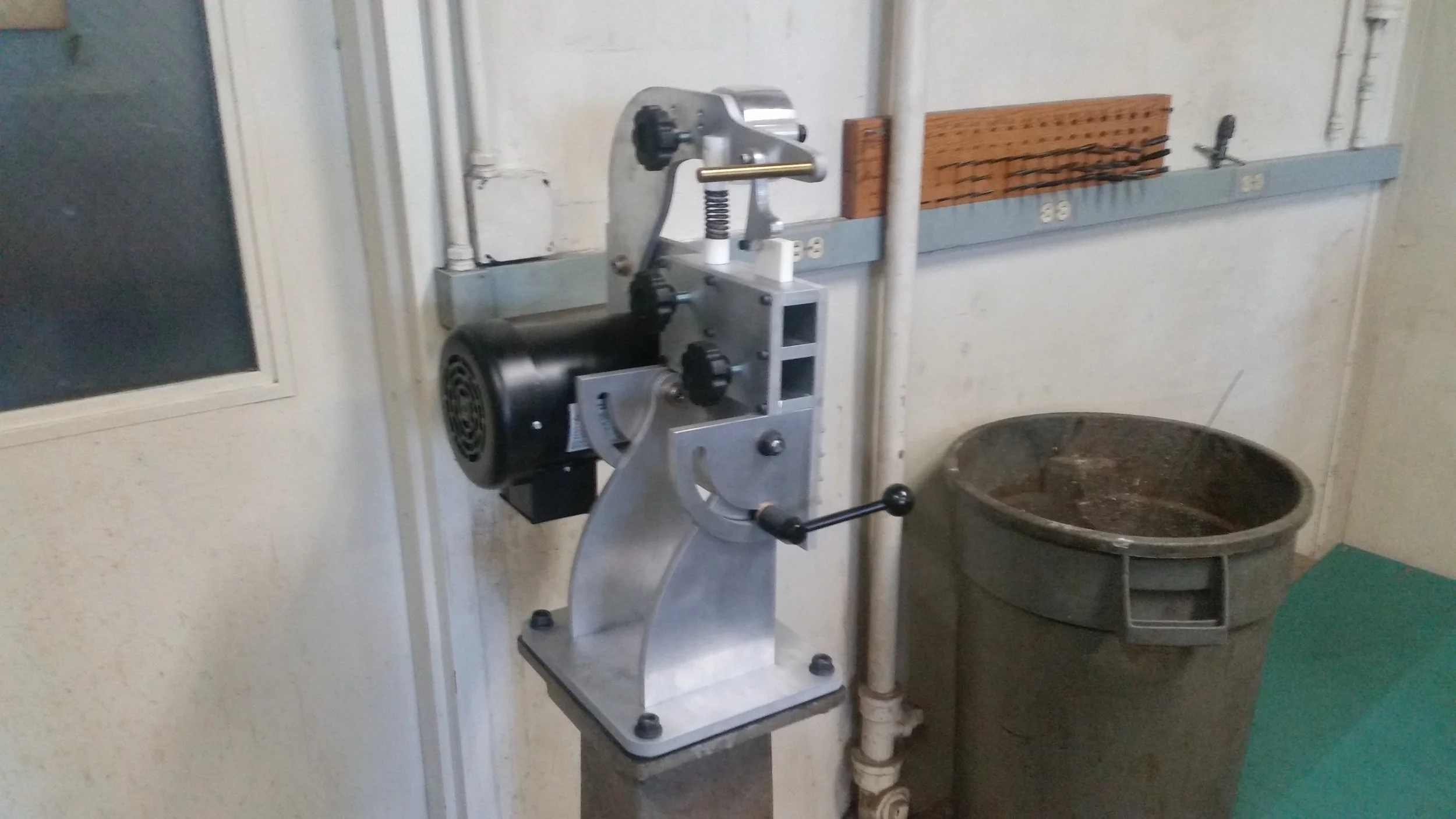
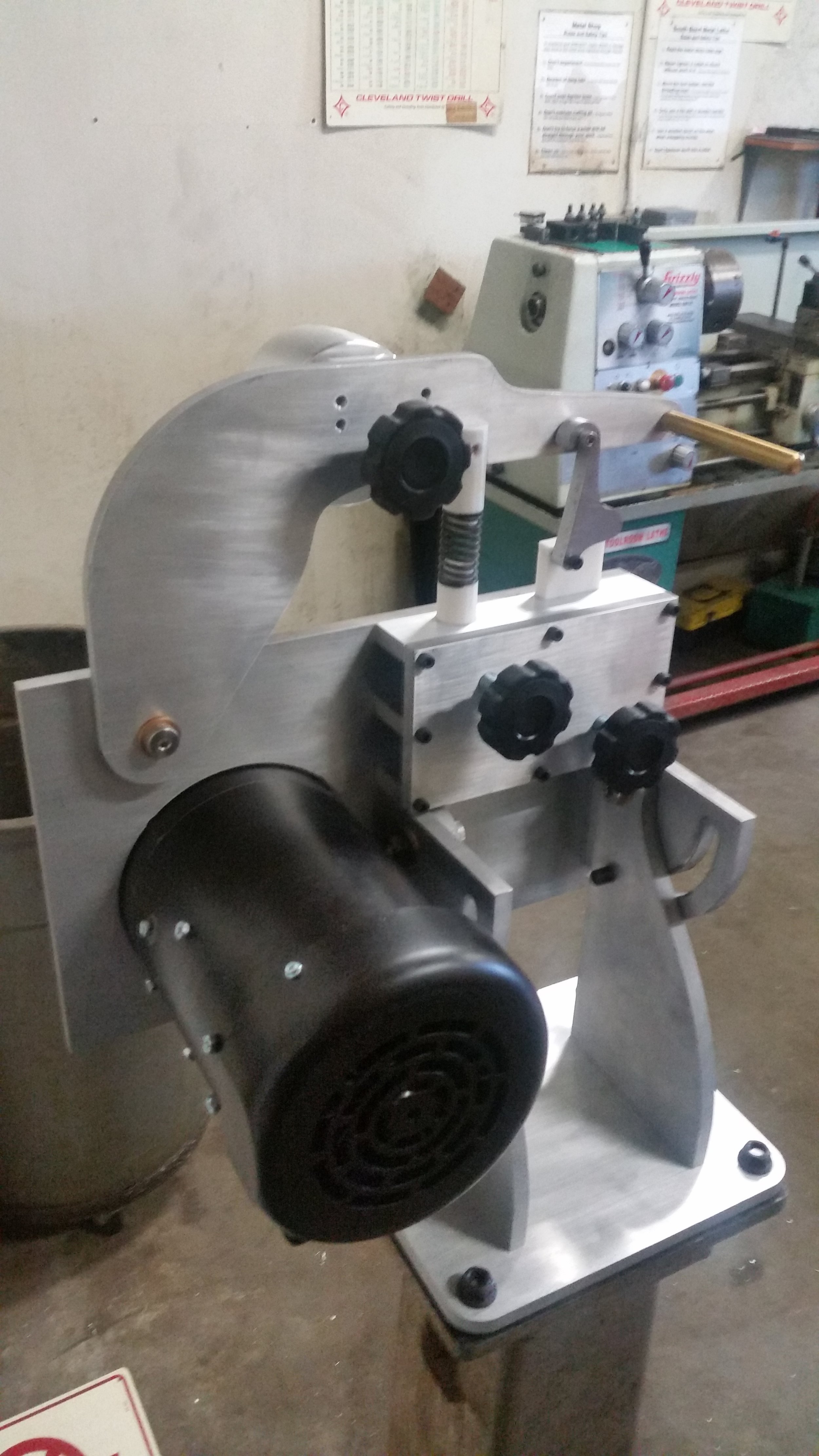
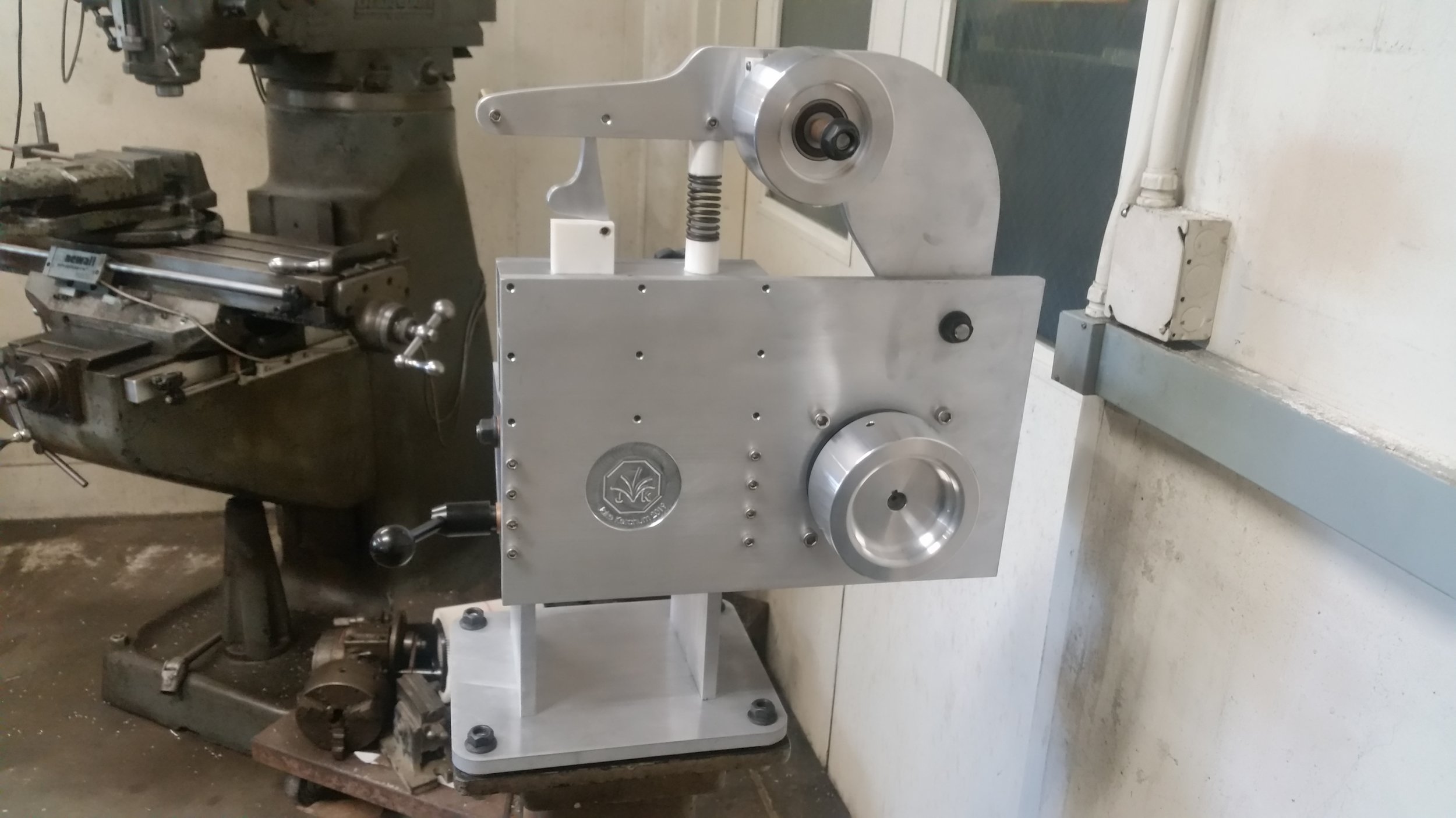
The grinder, fully installed in its temporary home. At this point the structure, and most of the mechanisms are together. Though the tracking adjustment and spring tension will need to be tuned in after the platen build is complete.
All things being equal, the assembly process was remarkably painless. All told the assembly took about 3 hours and, for me, really validates this type of waterjet + drill press construction as a way of building/prototyping large structures. I have included a summary of my process below for anyone looking to build a similar grinder (and for my own reference).
I started out by using 220 grit sandpaper to give the parts a decorative “brushed” finish. This largely produced the aesthetic I was going for, though on some parts I did have to step down to 80 grit to remove some burrs and nicks. I then washed all the pieces with soap and water, after using IPA to remove the leftover sharpy and marking dye.
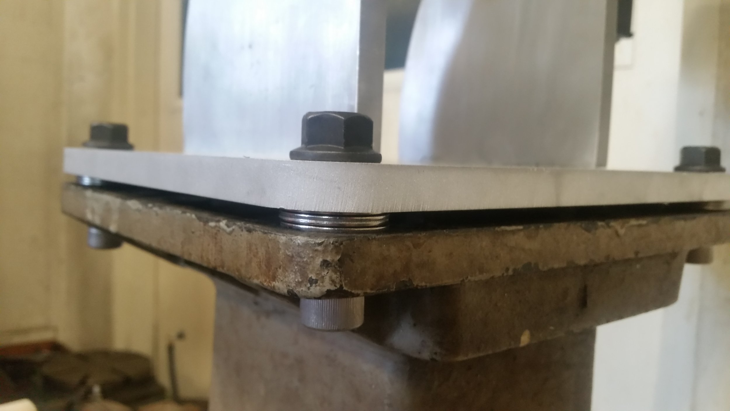
I then clamped the base plate in place above the pedestal ( a lovely Stanley grinder stand we have left over from a dead grinder) and used a hand drill to drill mounting holes in the base, with the corresponding base plate holes as a guide. This worked well, but probably should have been done before the cosmetic touch-ups.
I then separately assembled the pivot arm, back-plate with pivot plates, and base with pivot legs. I tightened down most of the bolts, but in retrospect ought to have left the back plate bolts somewhat loose and tightened them after assembly.
With the base and back plate together I then assembled the pivots. This proved tougher than expected, largely because the washers kept falling out. Not a big deal, but if I were doing the build again I would absolutely print a small fixture to hold then in place.
At this point it was easy to add the tension-arm, vertical and horizontal arm plates, and various knobs. The grinder was then moved to its final spot on the Stanley pedestal and screwed down.
Getting the motor on took two people (my thanks to Nathan Barton), and might have been easier at an earlier step, though I suspect it would have been “fun” at any point in the process.
Water Jet:
This was my first water jet project, so I was very excited to try it out. All of the structural plates were cut to dimension on the water jet. For the holes, I used the water jet to cut pilot holes and then drilled/tapped/reamed them afterwards with a drill press. The process was virtually painless, and I would certainly consider it in the future for low tolerance / non-cosmetic parts.
The plates were organized into two panels, each 1’ by 4’, to correspond to the 1/2in aluminum stock I purchased for this project. This didn’t leave me quite enough stock to completely build a second grinder, but did provide a nice buffer in case of accidents or for fabricating multiple bases as needed.

Drill Press:

Playing with the main shop’s new laser guided drill press. Turns out the lasers need careful alignment before use, but it’s a neat idea.
Although the water jet is great for cutting profiles, it just doesn’t have the precision for tight tolerance holes, particularly not where they need to act as bearing surfaces of any kind. To provide better hole tolerances I drilled out all of the water-jet holes on the drill press. The 1/4in holes were cut at 1400RPM with standard jobber bits from Mccmaster, and the 1/2in holes were cut at 750RPM using the same type of drills. The 3/4in reamed holes were drilled/reamed at 550rpm. That seemed to be a bit fast for our tooling, but worked well enough in the end.
A special shout-out to the main ME shop for picking up some 3/4in reamers without which this would all have been much more difficult.

The vertical arm plate. I find that writing the intended operations directly on the plates helps cut down on confusion.

All of the pivot plates (and the vertical arm plate) before drilling.
Manual Mill:
The two pivot legs, and two pivot plates, all mount to their respective bases using 1/4-20 holes drilled and tapped into their bottom edges. This will hopefully give me a nice clean interface without taking up too much space or resorting to adhesives. Both parts were designed with a flat reference edge, which I used to align each part in the vise. I then established a reference zero on the (+X, +Y, +Z) corner with an edge-finder and drilled the 4 tap-drill holes on each part. The threads were cut by hand with the part still on the machine.
Story: While spotting my final set of holes the HSS drill snapped off in my part. I was subsequently able to simply cut through the remains of the bit using a 1/4in carbide endmill. I consider this sequence of events to be a lesson in both the hardness of carbide, and the importance of purchasing quality tools.

Using one part as a crude 90 degree reference for another. The copper block is to ensure only one of the two parts is clamped when tightening the vise.
3D printer:
Although not strictly required for a test fit-up, I decided to 3D print a few of the fiddlier tension and hold-down components to get a better sense for how everything will go together. These parts need to last through a few fit-ups, but shouldn’t see more than 3-4 hours of actual grinding use. With that in mind, I printed them with my standard settings (20% infill, .6mm walls, .2mm layer height) and all of the threaded holes enlarged to take heat set inserts.