Summary:
This is the latest (and most successful) in a string of attempts to create DIY dipping dots. I recently found the patent for Dipping Dot’s trays, so this is an attempt to re-create the same mechanics (same needles, pressures, ect) on a smaller scale.
This project was particularly interesting to design/machine, because everything needs to be food safe. That meant new materials, designs, and finishing requirements.
Results:
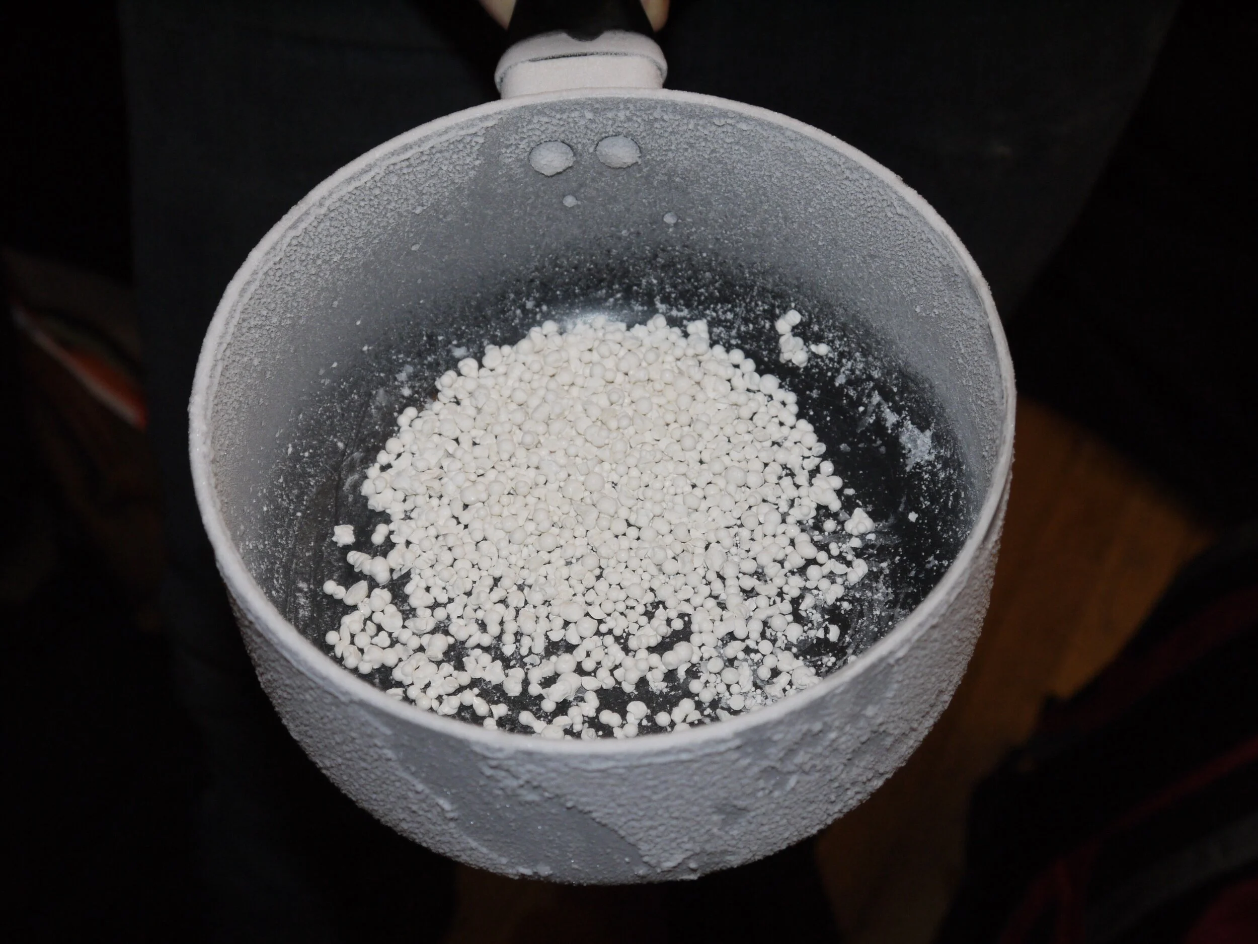
On the whole, I thought this attempt went rather well. Getting the LN2 side of things dialed in took some work, but once that was sorted we were able to reliably create 2-3 cups of well formed dipping dots per pitcher of LN2. Overall mess was high, but manageable once we started putting a cup beneath the device when not in use.
The majority of the dots were around 2mm in diameter, and generally formed in clumps of 1-3. This is a bit smaller, and a bit clumpier than I would like, but certainly an improvement on my previous efforts. Overall taste and mouth feel were good (once they’d warmed up), and I think with better LN2 control this method could produce top quality dots.
Process:

The mess: manageable, but certainly non-zero.
The method I arrived on for this round of experiments was holding the device above a plastic pitcher of LN2. Once the pitcher’s supply of LN2 dropped to 3in I would transfer the LN2 and dots to a pot. They dots would then be tapped lightly with a spoon to encourage cluster separation. I served the dots directly out of the pot, and thus did not test storage.
The overall process runs as follows:
Rinse system under sink for 5 minutes.
Produce a batch of ice-cream base, and flavor.
Hold the device above more than 5 inches above a pitcher of LN2, and add fluid.
Move the device in a circular motion, periodically moving the device away from the LN2 so existing dots can drop out of the recirculating LN2 column.
When 3 inches of ln2 remain, poor out the dots into a pot or pan and lightly tap the dots to break up larger clumps.
Wait 3in and serve!
Run vigorously under the sink for 30 minutes, periodically adding dish soap.
Future Work:
The cleaning process. We got better/faster results with more vigorous water input then shown (Bubbles circulating is a good sign).
At the moment, I think the biggest area for improvement has to do with LN2 management. A better insulated, or even double-chamber, LN2 container might recirculate less, promoting individual dot formation without collisions. Adding a screen, or deliberate current to pull newly formed dots away from the dot formation area could also help. One screen geometry would be an inverted cone such that dots fall below the screen but cannot be pulled back above it to collide with new dots.
A different, but promising, avenue of development might be pulsed pressure control. By narrowing the needles, and pushing fluid in through the upper cap in spurts we could force the formation of one droplet per fluid/pressure pulse. This method is mentioned in the patent, and could be a good way to promote the formation of larger droplets.
Resources:
Design Elements:
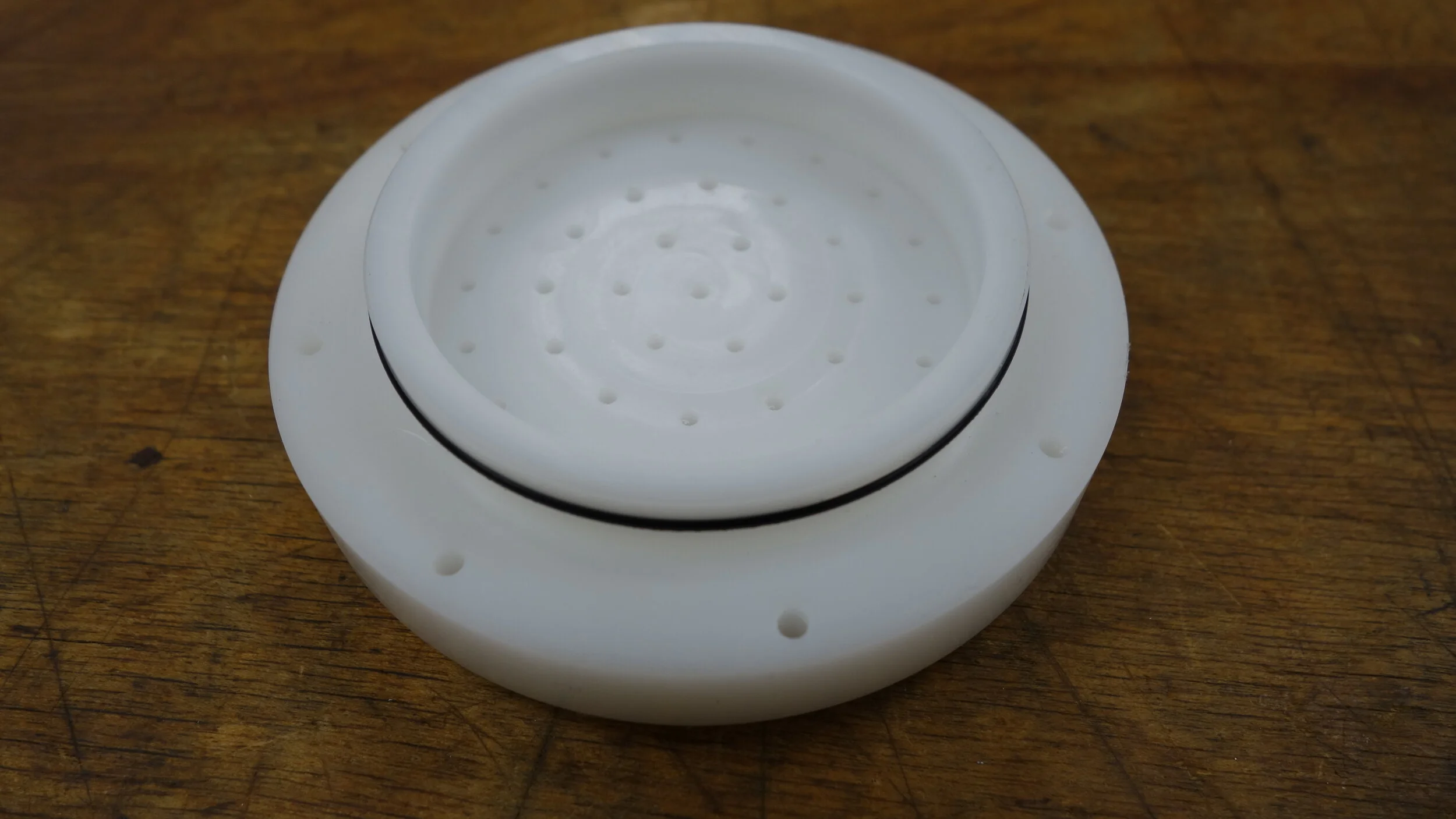
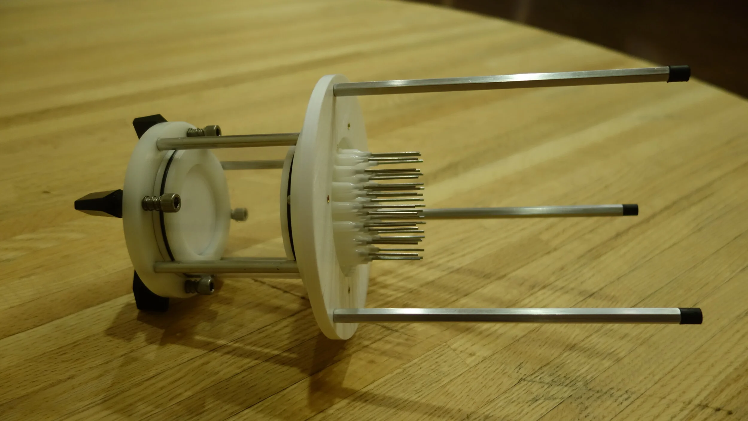
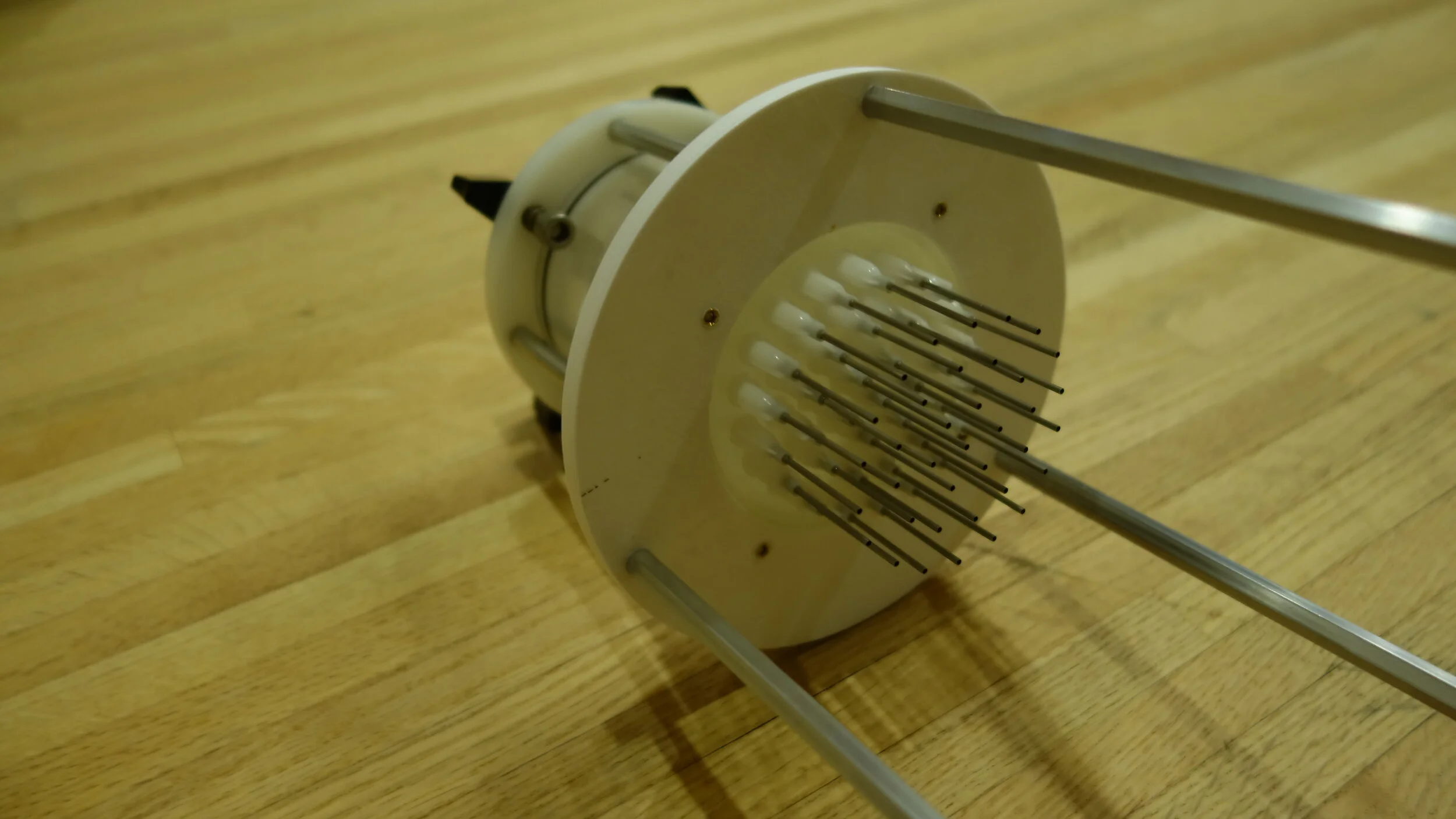
Luer Slip needles: I milled 39 luer slip connections into the bottom of the lower cap. This allows me to remove needles for cleaning, or to change sizes. During testing I found that the composition of the fluid - unsurprisingly - has a big impact on how quickly dots form, and how big the dots end up being. Frozen yogurt might require larger needles, and juice dots will certainly require a smaller one. This was the longest, and fiddliest, part of the build, but definitely worth it for the versatility.
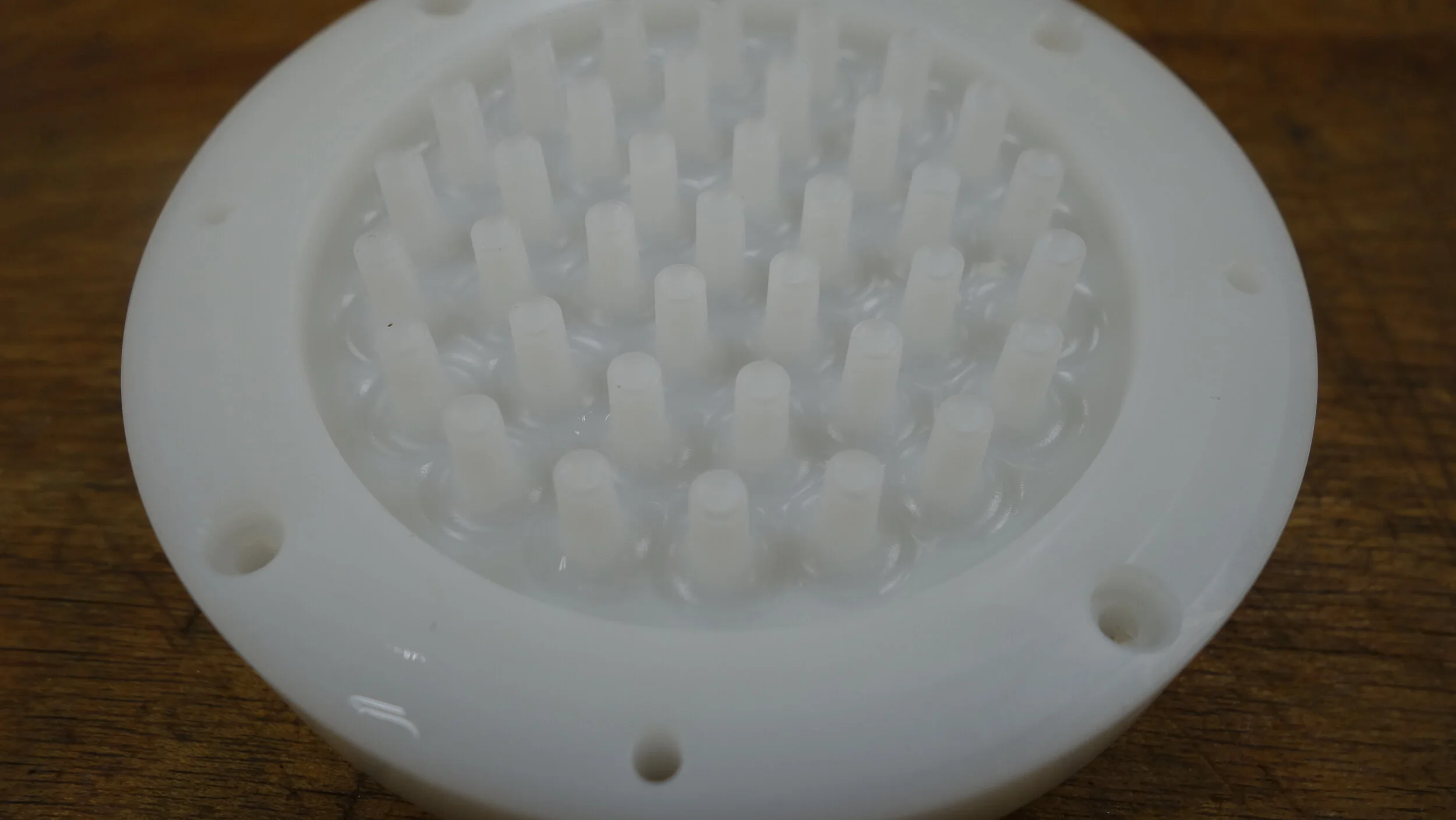
The needle interface was machined as a single contouring operation with a 2 flute 3/16 carbide ballmill. I used a 20 thou step-down, with no roughing pass. This was a long operation, nearly 3.5 hours, but produced a spectacular surface finish.
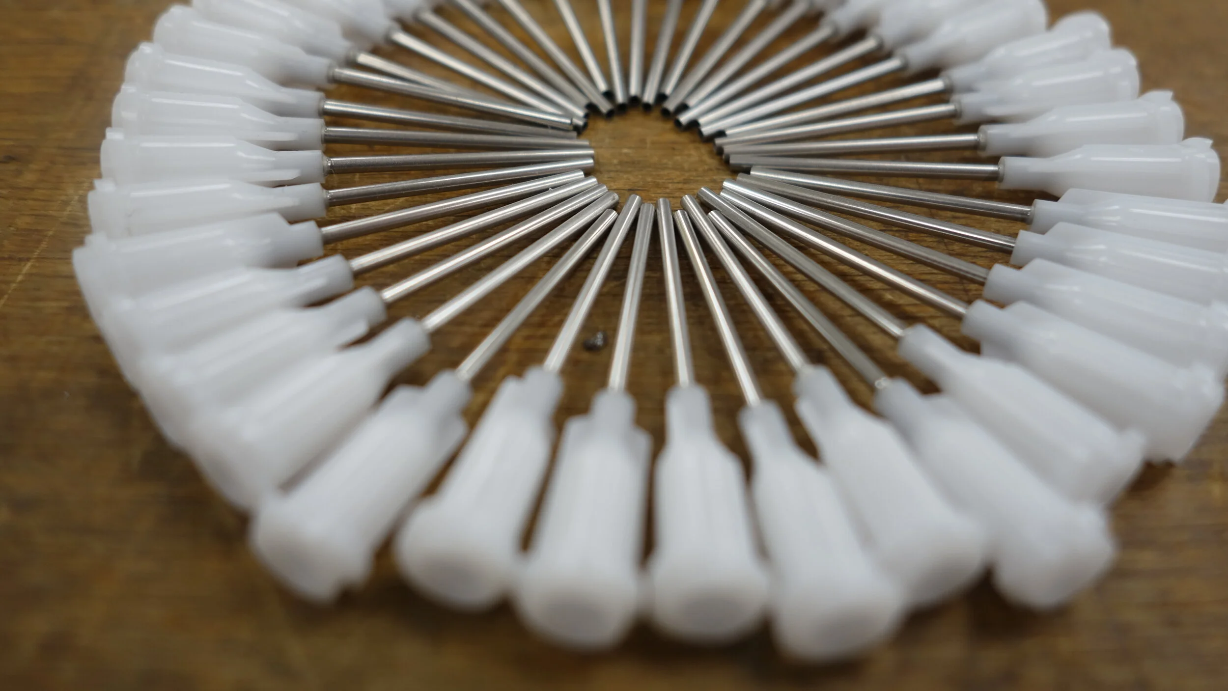
All 39 needles arranged in a circle. I used one inch, #17 dispenser tips, which fall right in the middle of the #16-#18 range called out in the dipping dots patent.
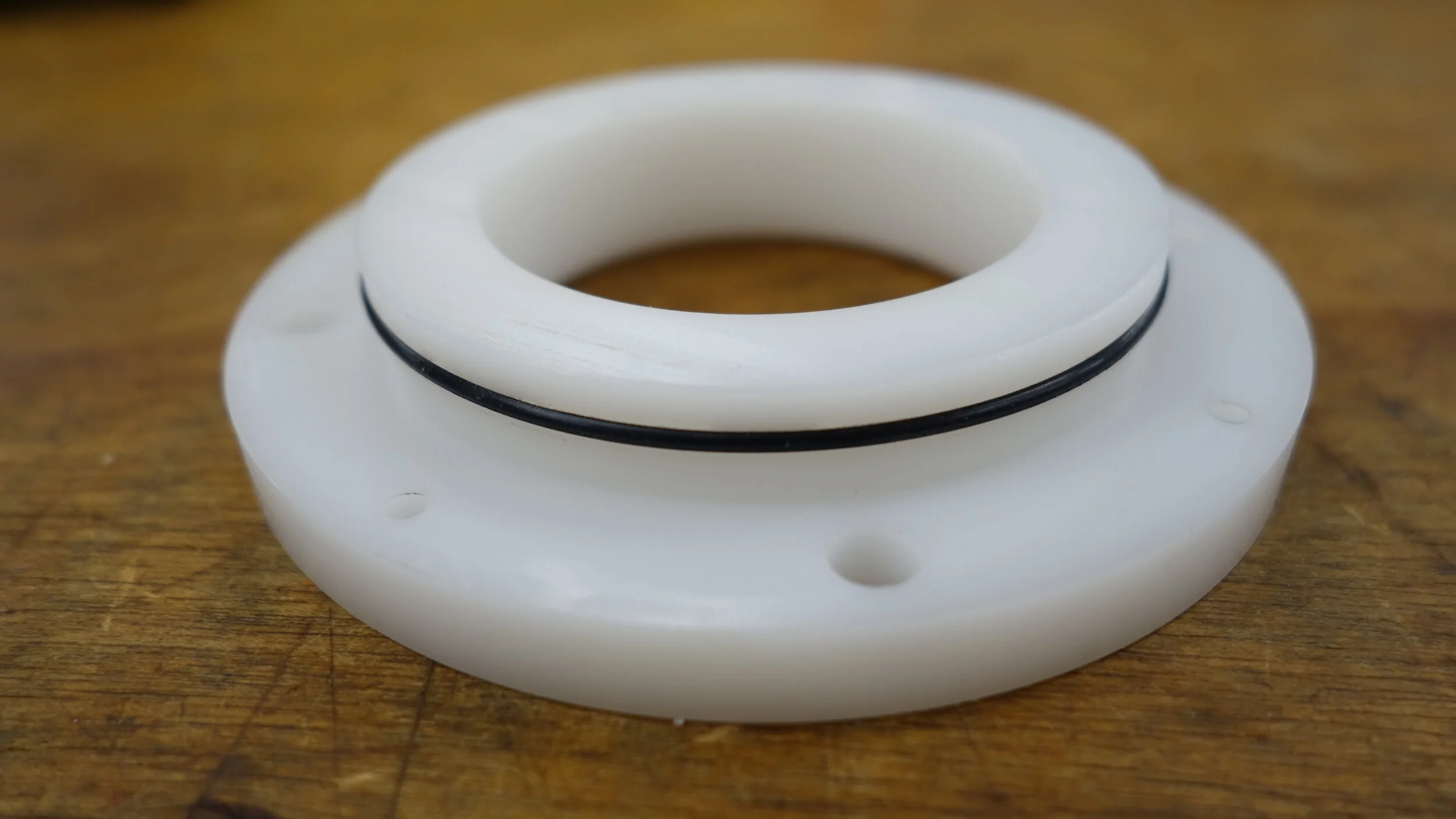
Seals:
One of the cool parts of this project was getting to play with seals for the first time. The upper and lower caps both use a #39 Buna-N O-Ring with corresponding standard groove geometry. I was delighted to discover that this worked exactly as specified, and sealed the chamber nicely with no additional features. The groove itself was cut with a woodruff cutter, and I did slightly chamfer the top and bottom of the clear cylinder to ease assembly.
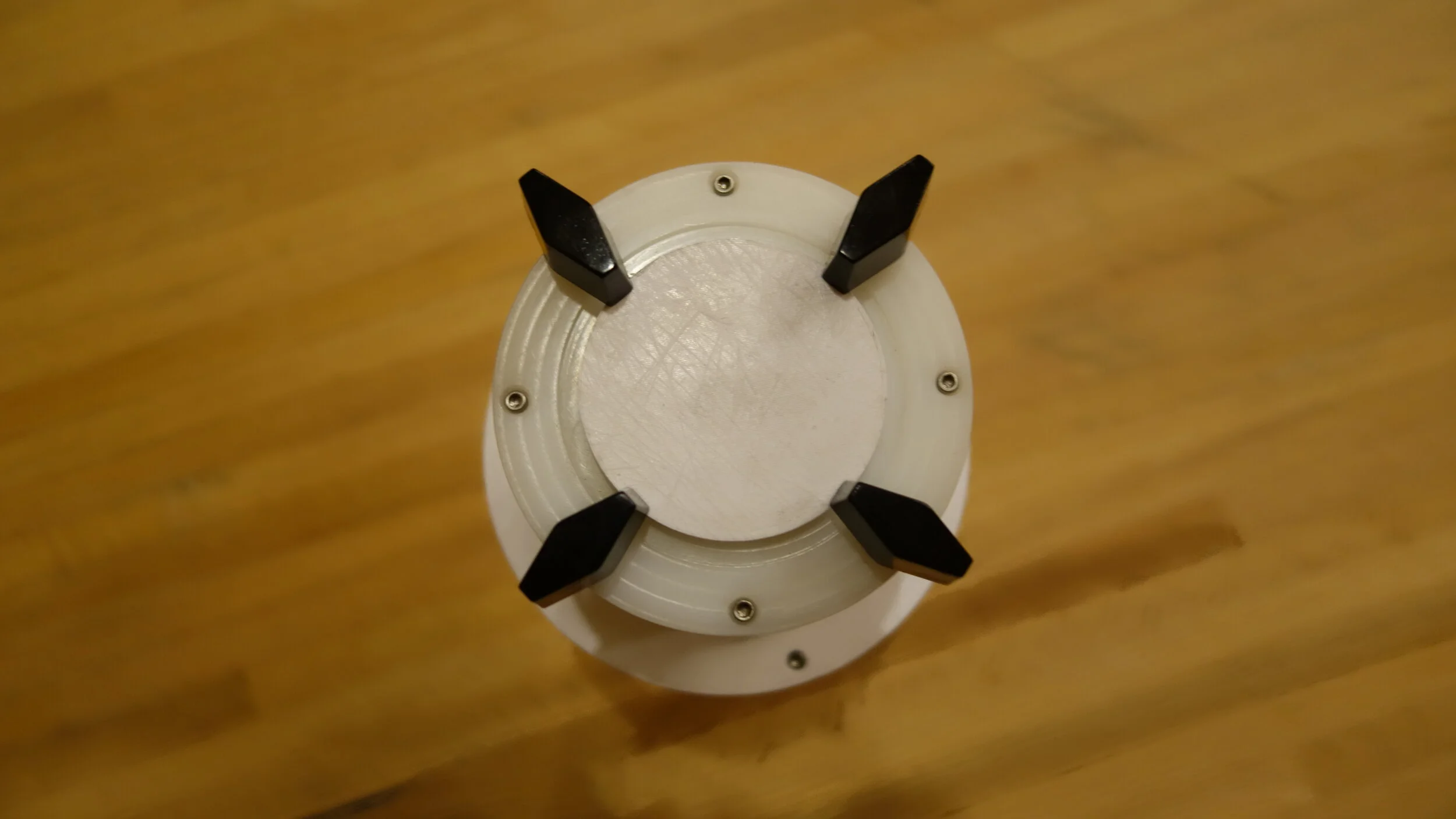
Inner Lid and Clamps:
In the long run I want to try using active pressure variation to generate the dots. For that reason, the chamber is equipped with an inner lid, into which an air - or cream - inlet can be mounted. The cap is designed to use a #32 o-ring seal, in a similar fashion to the #39 seals between the outer lids and chamber wall. The 4 knobs are designed to help retain the cap when under pressure. Put together they provide enough force to counteract about 5psi (well more than needed), and can be disengaged easily by turning them out of the way. This cap was printed, but never fabricated and may be part of later posts.

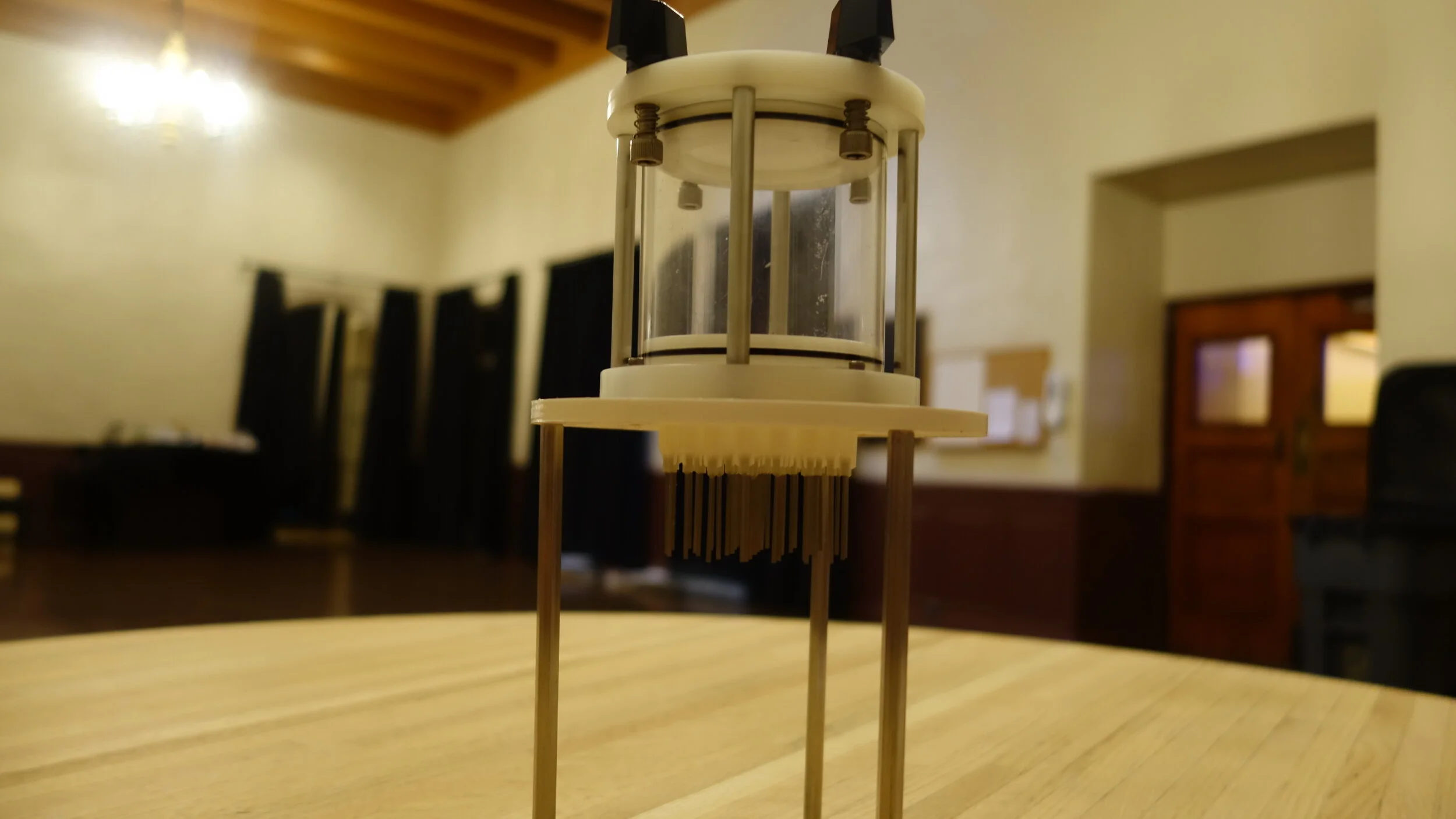
Stand and legs:
The chamber sits on a 3D printed ring supported by 3 legs. This works okay, but is one of the design elements I am least happy with. In practice, the legs are a bit too close to fit around most pitchers, and a bit too short to avoid freezing the needles. With that said, the core idea of combining standoffs with mccmaster feet worked well, and I will certainly re-use that for future builds.
Fabrication:
This project had four custom components as follows. All of the rest of the parts were purchased off of mccmaster carr. Delrin, polycarb, or stainless was used for all components in the food path. Buna-N was used for the o-rings. Some of the supporting structure are aluminum.
Custom:
Lower Cap - Machined out of Delrin.
Upper Cap - Machined out of Delrin.
Cylinder - Cut from polycarb and belt sanded to length.
Stand ring - Printed from PLA.
Mccmaster Carr:
Knobs: 6477K57
Springs: 9435K5
#32 O-Rings: 9452K119
#39 O-Rings: 9452K127
3” standoffs: 93330A541
#17 dispensers: 75165A243
Polycarb Tube: 8585K39
6” standoffs: 91780A562
Bumpers*: 93115K95
4-40 screws: 92196A108
*For future builds use the hard variant.
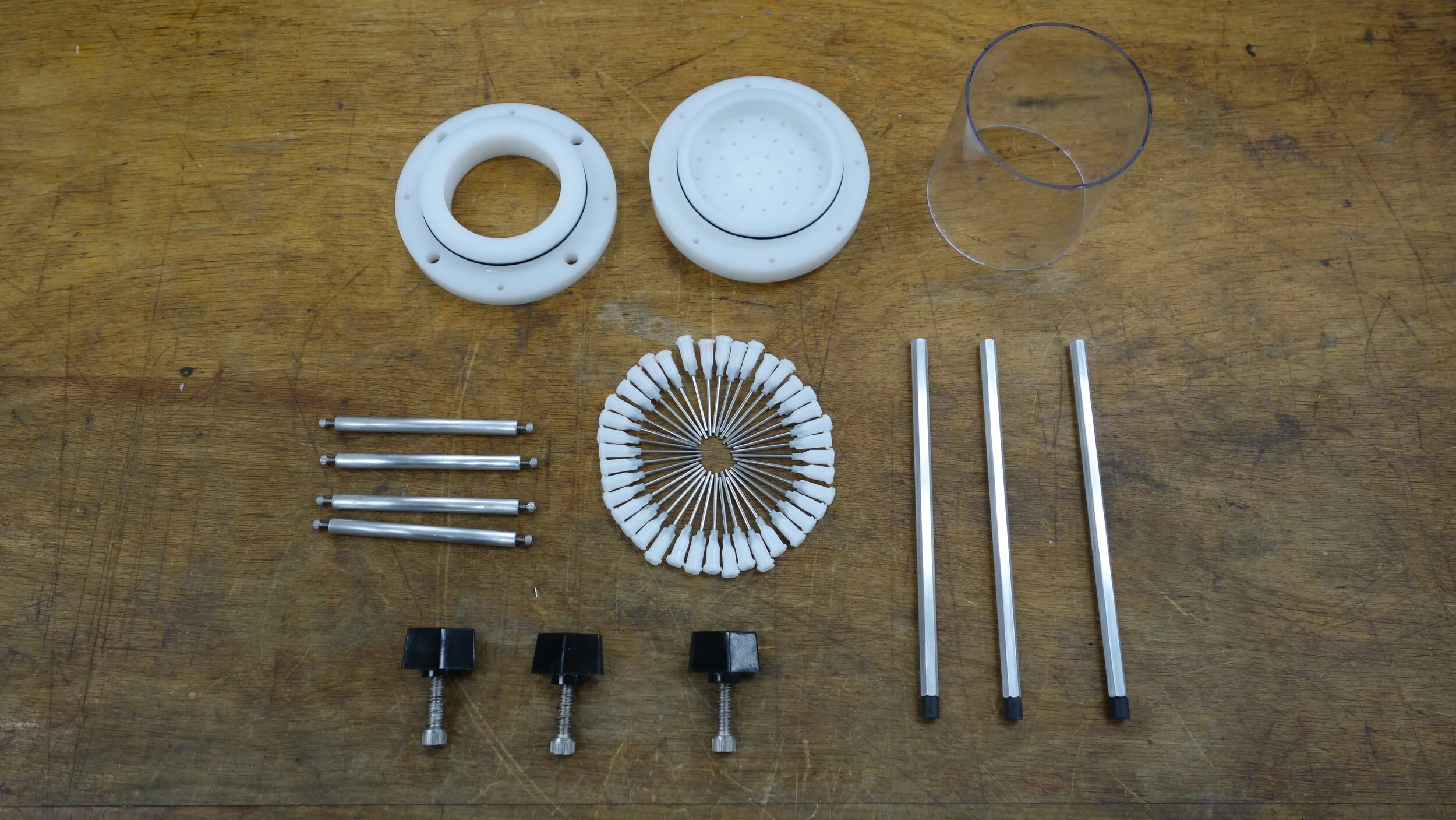
Most of the parts laid out for assembly. Missing are the 3d printed components, and the screws that hold the legs on. One nice thing about this project is that their are very few fabricated components. With the exception of the upper and lower caps all of the core components can be purchased from mccmaster or 3D printed.
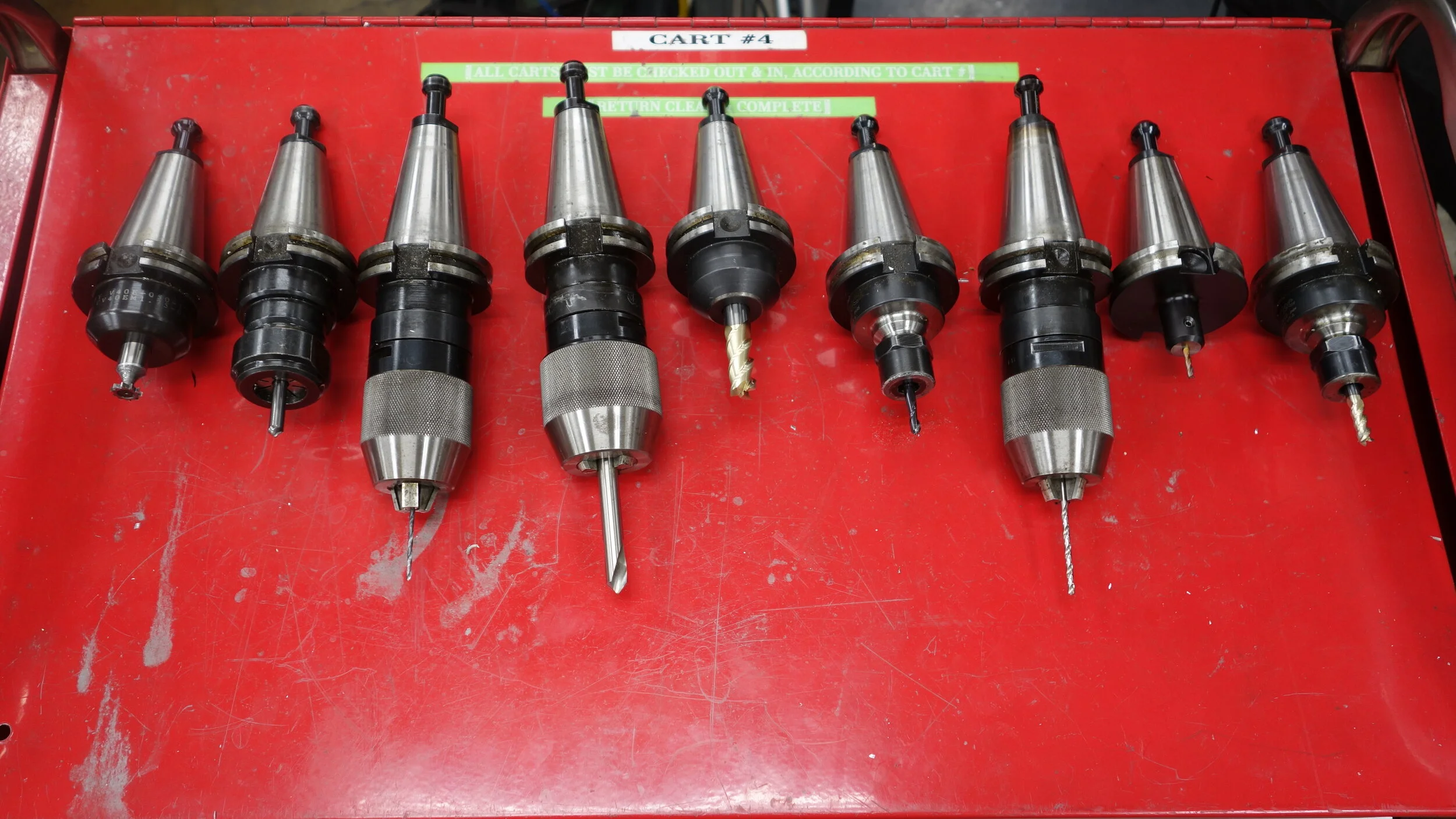
The tools used for cutting the upper and lower caps. You may notice some of the tools are designed for aluminum while others are designed for steel, at the feeds and speeds I am using none of the coatings or geometries work particularly better than the others.
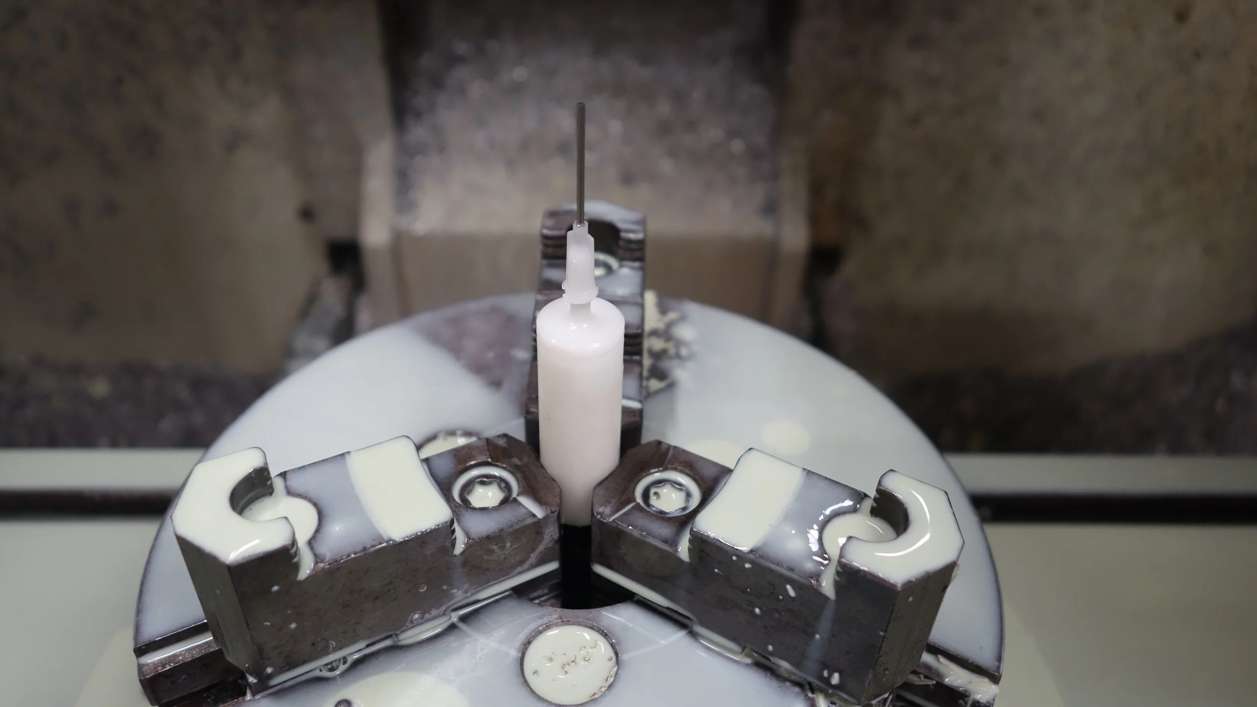
A prototype for the luer slip connections and o-ring grooves. I later took this over to the lathe and added a bore so it could serve as a syringe.
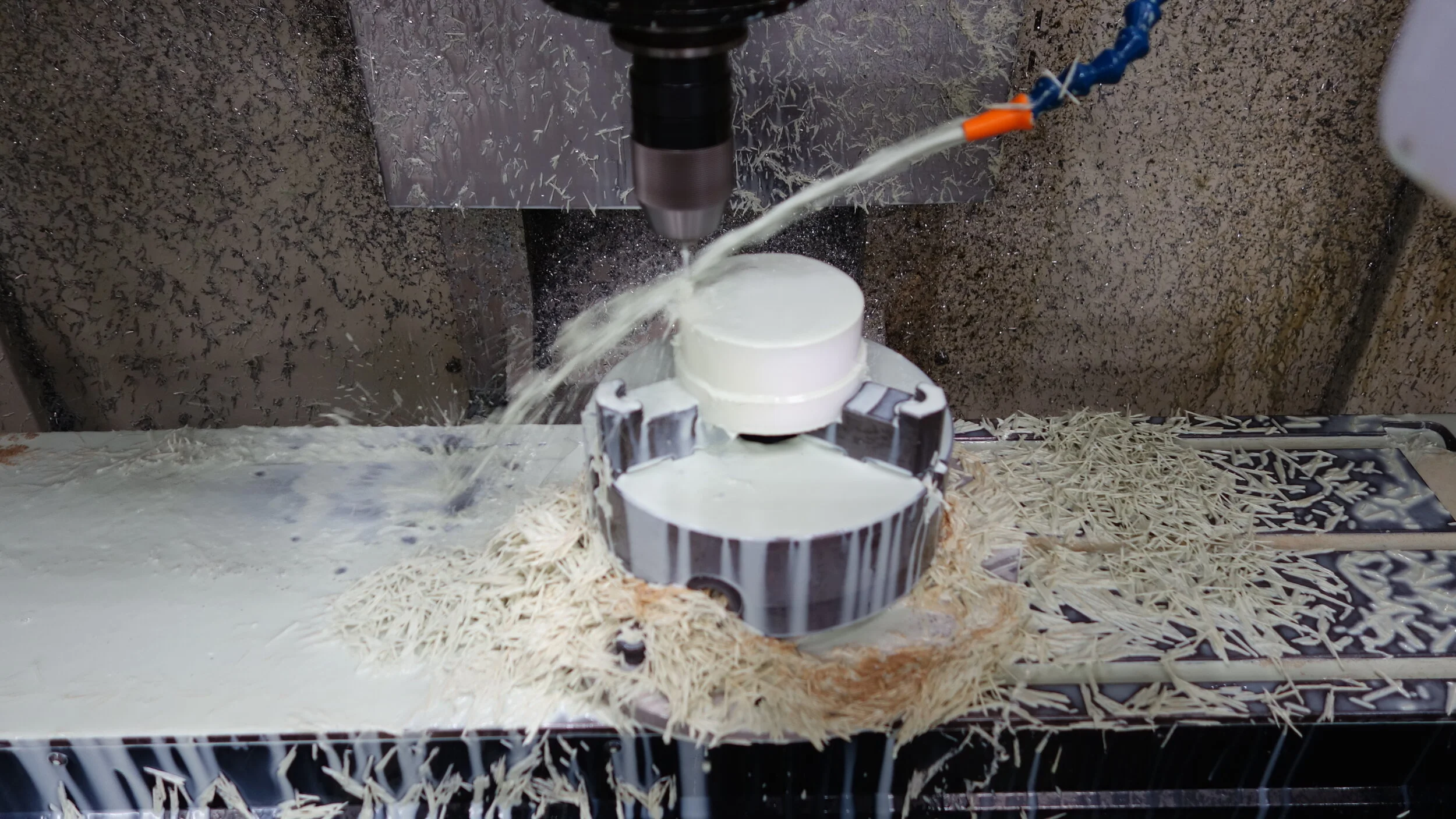
Cutting the OD of the upper cap.
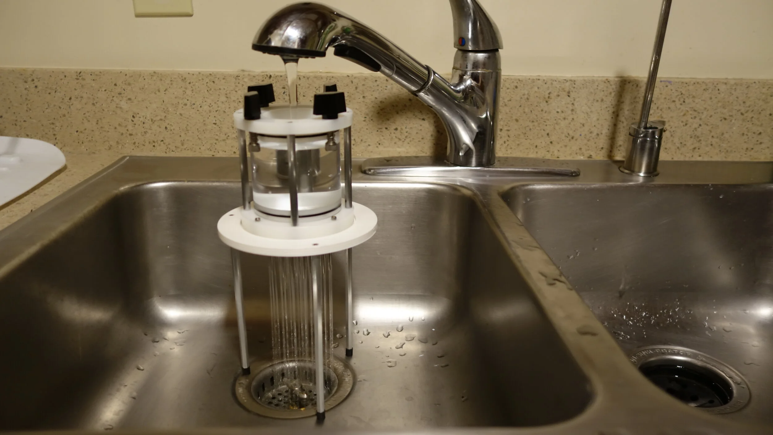
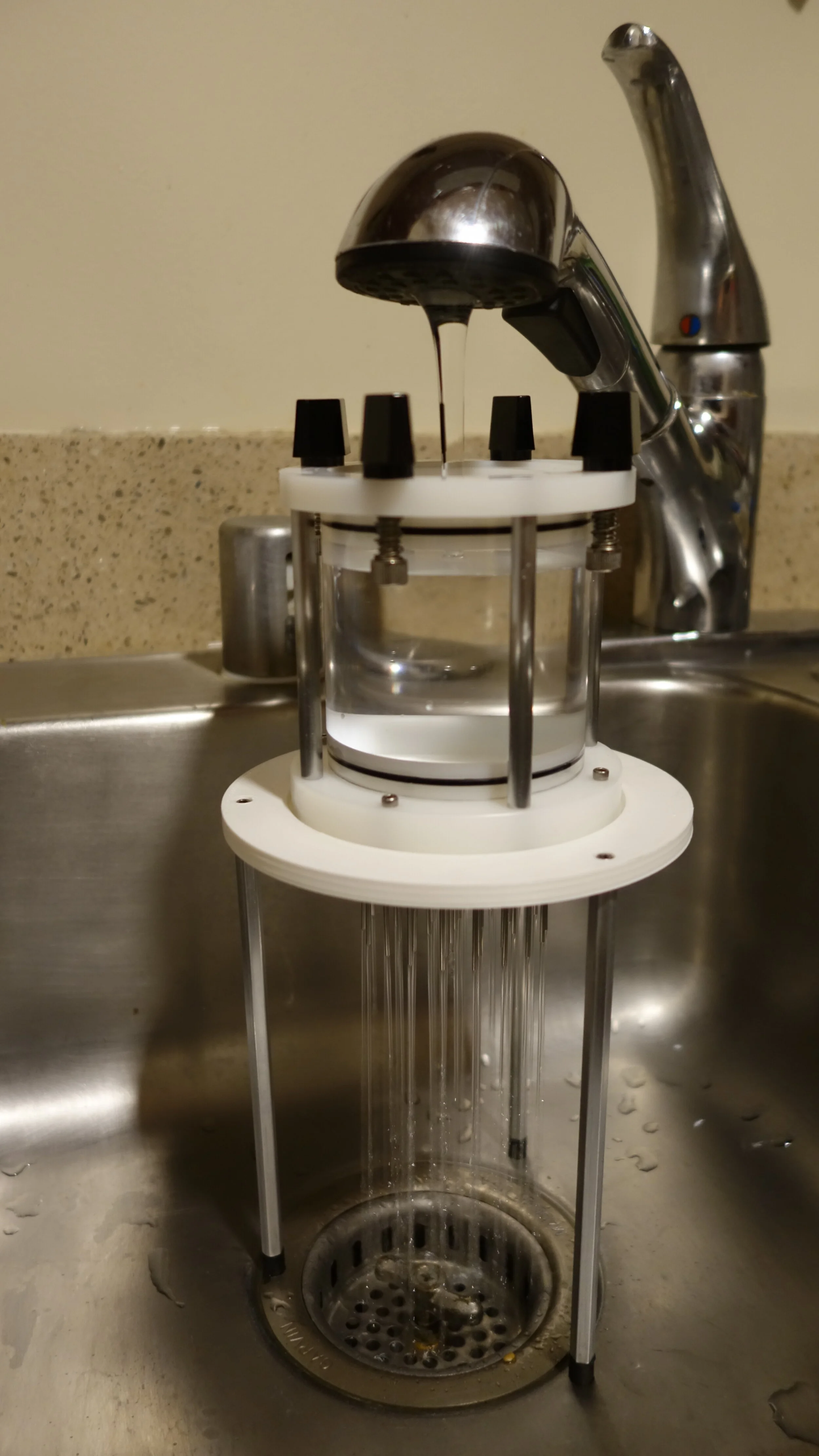
Before using the device for food I ran it under the sink for an hour to clear out all traces of coolant.
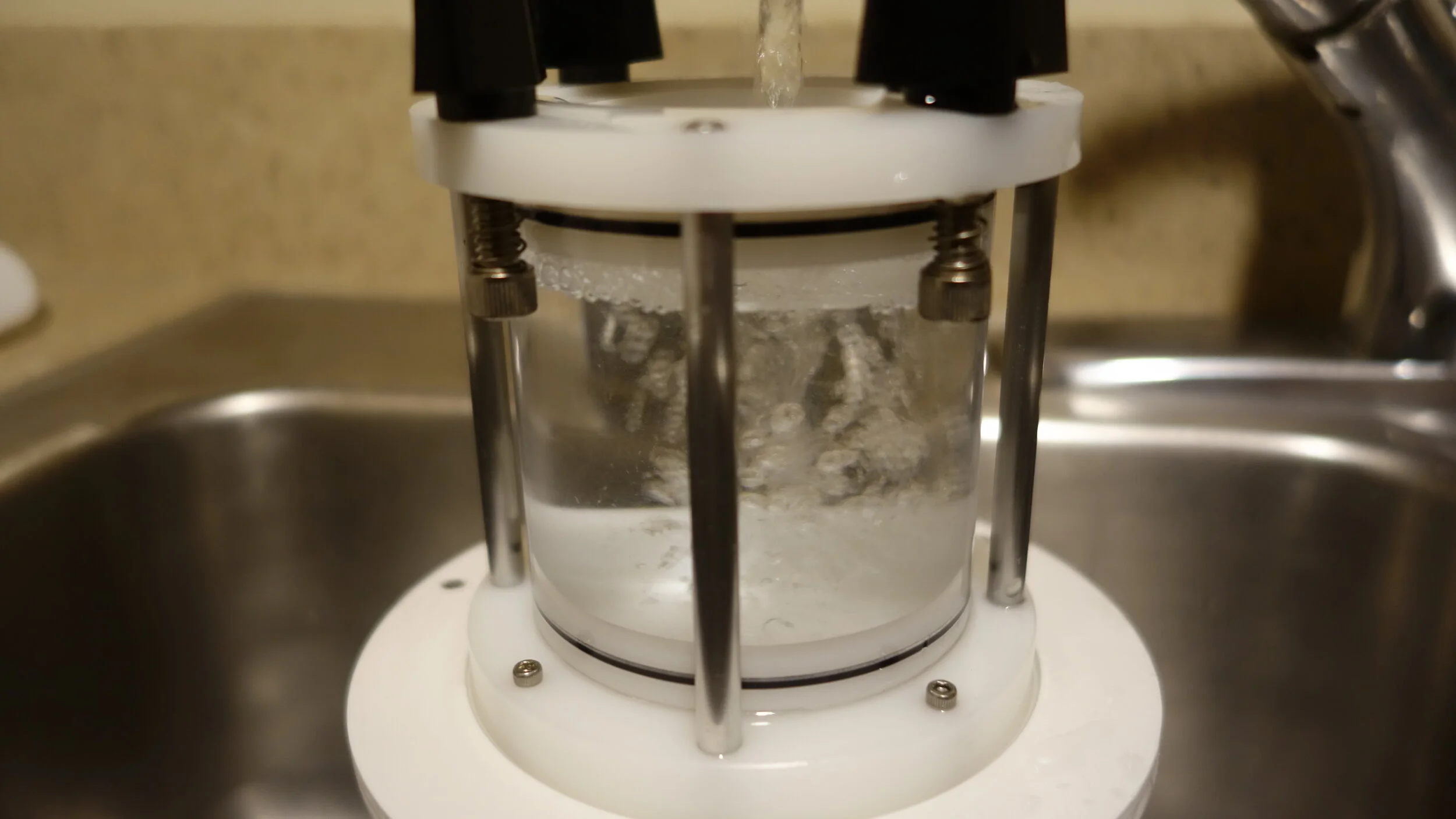
After using the device I found that heavy recirculating flows like the one shown produced the best scrubbing effect.