Home Improvement / Hell Lighting: Living Room Lights

Summary:

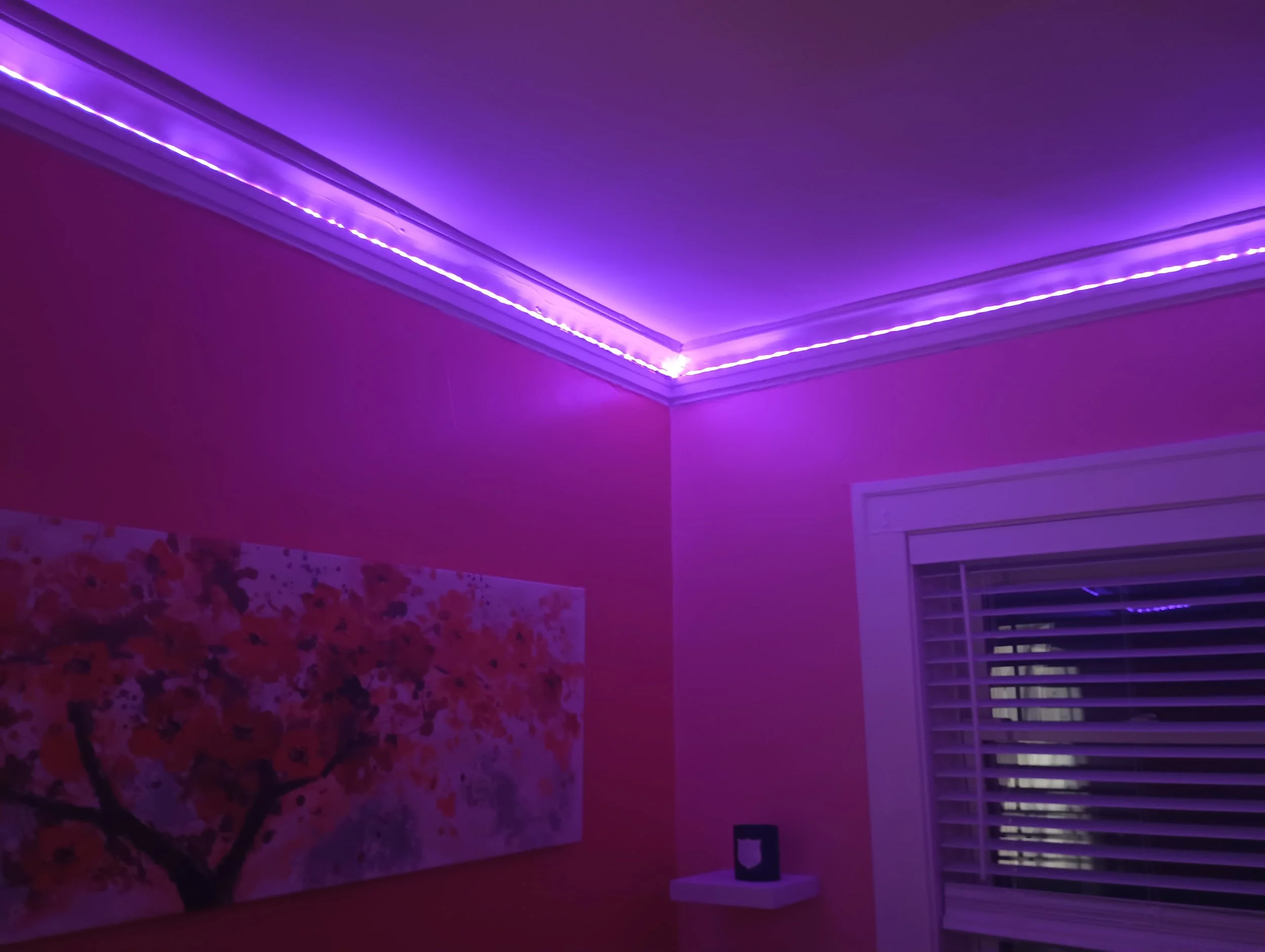
An LED lighting system for the living room of our new apartment! So far we are about a week in and I’m loving the little bit of extra flair, plus it makes a pretty great night light.

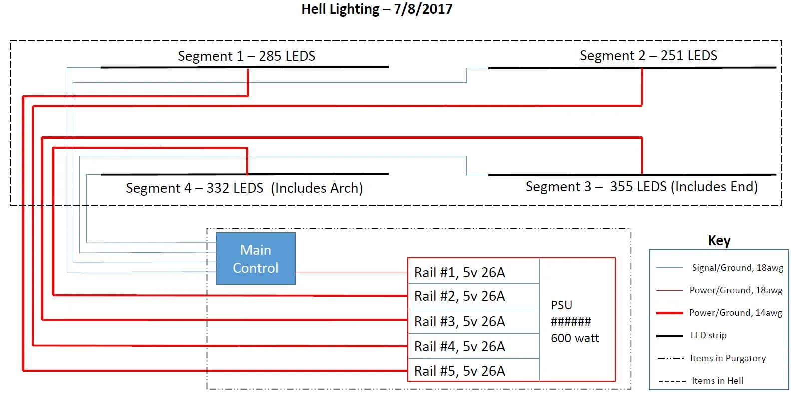
I’ve put up similar systems in a few places, but this is the first setup (excepting the original) that is a complete display with 4 sides, permanent wiring, and support for all the existing patterns. Now that it’s up and running I plan to start writing patterns again, and maybe even roll out a V3 controller if the extra memory / sensors ends up being necessary. I have temporarily scrapped the multi-controller version of the firmware as too complicated for not enough added flexibility.

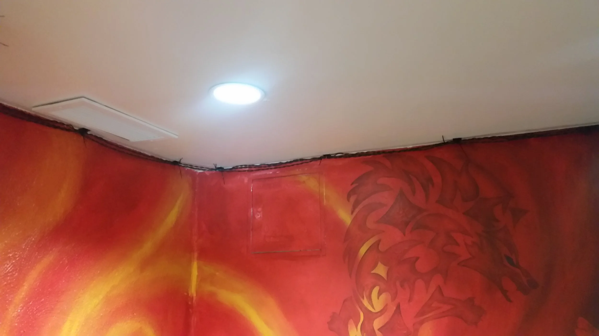
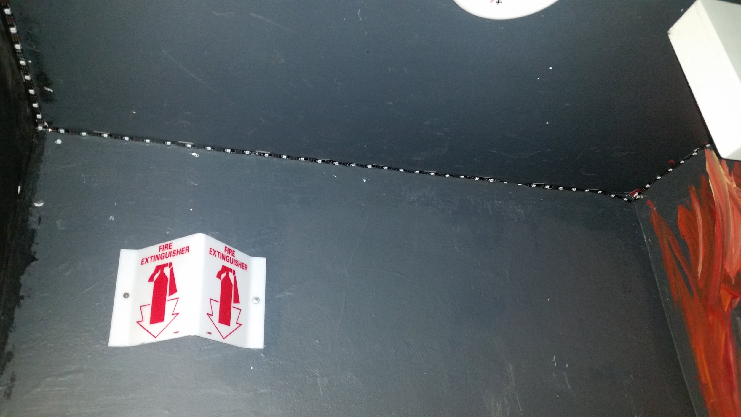
Our living room is a much smaller space than the Alley of Hell at Caltech, but with double-density LED strips still have 967 LEDs, just a hair under 80% as many as the original system. I like the higher density (60 leds/m instead of 30leds/m), and I particularly like how we were able to run the strip inside the molding. It gives the install a softer, more organic, look and the effect is definitely something I’d aim to duplicate in future systems.

Software Tweaks / Layout:

Unlike the original, this system uses two strips instead of four, and both strips originate in the corner we want to make the top right. To accommodate this we zero’d strips 2 and 3 in the config files, and updated the lengths to match the installed LEDs. We also updated the mappings for the two walls and two end caps to match the new room. I find that the race pattern is great for that process because it so uniquely identifies the four regions.

New Patterns:

We have one new pattern associated with this install “white”, which just displays white across the whole strip. The potentiometer controls the brightness, and it makes a nice night-light for folks who are sleeping over. It also doubles as our “off” pattern when the pot is turned all the way down.

A downside of using two end-powered LED segments (as opposed to 4) is that we see some color aberration towards the end of the strips for bright patterns. Since the strips are the same length the color shift is symmetrical at the interface point (which hides it a bit), but it does mean we have to be careful about patterns like “white” or “rule 101” that generate lots of all-white LEDs. The sparser patterns like “purple”, “trains”, or “morise code” are not impacted.

[Hell Lighting] Control Board V1

Overview:

Hell Lighting is controlled by a MEGA ADK mounted at one end of the hallway, adjacent to purgatory, where the power supply is stored. This is a custom "shield" to sit on top of the mega and provide IO terminals as well as basic control elements for the system. This pcb replaces the prototype unit used during Hell Lighting's trial period and, with the new pattern system now online, represents the last component required for us to declare the system fully operational. 

Although this shield is primarily intended as a control board for Hell Lighting provisions were made for it to act as a generic pattern controller. With that in mind, the board can run up to 670 LEDs, split between the four outputs, directly off of the power input terminals. For more information about independent operation and system current limits see the testing section below. 

Note: Although this board is installed and working there are two required reworks in order to use the board with the interrupt based version of our firmware. In particular it is necessary to connect Pin 15 to Pin 19 and Pin 16 to Pin 18 all effected pins should be set to inputs. 

Features: 

  • Pattern Switching: One encoder to switch between patterns, with a built in button for resetting the current pattern. 
  • Pattern Control: One potentiometer connected to an ADC input, and a button connected to an interrupt pin. 
  • Screw Terminals: Four terminals for connecting patterns (GND, DATA, 5V), and one power input terminal (GND, 5V). 
  • Display: One monochrome 8 bit bar graph for displaying the current pattern or debug info, and a power indicator LED. 
  • Sensors: I2C temperature sensor with 1 degree accuracy and 12 bits of precision, front mounted. 
  • System Control: Reset button, programing jumpers to issolate the arduino from power and ground. 
New board right before installation/cleaning. 

New board right before installation/cleaning. 

The old board... We don't talk about the old board. 

The old board... We don't talk about the old board. 

Firmware: 

Although this board is mostly just a cleaner version of the V0.1 board we were already using. There were a few features which needed to be enabled in firmware. A brief description of how each of these was handled can be found below. If you want additional details, please don't hesitate to reach out. 

All the best things come in parts bags.

All the best things come in parts bags.

Encoder: 

The encoder is responsible for controlling pattern changes, and is handled by an interrupt triggered on it's "B" pin. Each interrupt determines the direction the encoder is moving by comparing the values on A and B, then records a CW move if they are the same and a CCW move if they are different.

Even with hardware de-bouncing it is worth implementing some kind of bounce management in software. I found it sufficient to wait 80ms before allowing another tick to be recorded. 80ms is fairly responsive, but tends to give false direction reversals. To combat that, I set the wait time before registering a change in direction to 100ms which seems to have pretty much eliminated the issue. 

Interrupt time on a 2560 running Hell Lighting is at something of a premium since interrupts must be disabled when writing to LED strips with a 3 wire bus. With that in mind, I found that using the interrupt to record, but not act on, pattern change requests and then updating the pattern at the end of each frame worked far better than directly updating the pattern in the ISR the way we did when pattern change was handled by button. 

Pattern Output:

One of the new features this board incorporates is an LED bar graph to show the current pattern number. Since there were no conveniently located digital IO pins I connected it to port K on the atmega2560. This port can be set to output using the DDRK register. The correct values can then be written to those pins using the PORTK register.

Note that the design decision was made only to connect the graph only to the K register. This means that although it is a 10 piece bar graph we are only able to support 256 distinct patterns. At time of writing, we have roughly 16, so I do not anticipate this being an issue in the near term. Never the less it will likely be modified in the next rev. 

Temperature Sensor: 

The temperature sensor for V0.1 is the backed by two classes. One is a generic Temperature Sensor class, and the other is specific to the TMP175. These will form the first two classes in the new HAL for hell lighting. The TMP175 is an I2C device, but none of our end users will ever need to know that. A (very) abbreviated breakdown of the two classes can be found below:

SensorTemp - The high level temperature sensor class is responsible for keeping track of the last read temperature as well as the minimum and maximum possible temperatures for that sensor. It also exposes a set of functions to return the current (read new) and previous (return last) temperature in a variety of common formats. 

TMP175 - The TMP175 class fully implements the chip's features, including: variable read precision, low power mode, and extreme temperature interrupts. It also overwrites a function from the SensorTemp class to actually get data from the device and invisibly handle setting OS when the device is in low power mode. 

Verification: 

For the most part when it comes to PCB specs I am pretty happy to take board houses at face value (plus or minus a generous safety margin of course). That said, when it comes to questions like "Will this catch fire" I really prefer to do actual testing whenever possible. With that in mind, I decided to destructively test main power traces on the PCB by connecting the control board to a variable powers supply and slowly increasing the current until a failure point was reached. Temperature data was gathered with an IR thermometer (calibrated at 24c). 

Conclusion: Ultimately, the board "failed' at 21A when the board reached 165C and the solder melted. In order to keep temperature rise to a more reasonable 80 degree increase I would suggest limiting current through the on board power distribution buss to 17A (this limit has no bearing on systems like Hell Lighting that have external LED power). 

Current VS Temperature.JPG
Current Test.JPG

[Hell Lighting] Wiring

It lives! The past few days have been a tiny bit hectic, but the main power and signal wiring for the system is now fully installed and operational. We still have a lot to do on the system control and safety certification elements, but for now the lights are up and running with a temporary controller (linked in the project page) and the final power supply. 

Layout:

Hell lighting V2 is composed of four sections, each containing approximately 300 LEDs. Each section is powered by a single 5V 26A rail of the main Cosel ACE650F modular power supply.  The control unit runs off the final 5v rail of the power supply, though it can be moved to one of the main lighting rails if we make the decision to add a 5th lighting section in purgatory. Power for the four LED sections runs through 14 gauge UL 1316/1452 THHN black copper wire in twisted pairs. While the control unit is powered off of similarly rated 18 gauge black wire wire. Power for each section is provided at a single point in the center of that section. We have found this to be sufficient, in practice, to prevent visible color aberration under normal use. Additionally, each power supply rail has been seperately adjusted to ensure a steady 5v at the point of use. 

Signal for each section is provided to the start of that section through an 18 guage ground-data twisted pair. This means that all rails share a common ground, and that arduino ground is the nearest thing to a system wide reference voltage as can be found. Note, that like the power wiring, all data wires are black. My suggestion is to use a 1.5v battery and multi-meter to identify which wire is which at both ends should it ever become necessary to make adjustments. For additional calrification, please refere to the diagram provided or feel free to get in touch. 

Mounting:

Power/Signal bundle mid-hell. Note the spacing to ensure LEDs are vissable

Power/Signal bundle mid-hell. Note the spacing to ensure LEDs are vissable

After our disastrous attempt to use nails frosh year, we decided to zip tie mounts and zip ties to hold the wires up this time around*.  For aesthetic reasons, we decided to keep the wires, zip ties, mounts, and heat shrink black to match the LED strips.  One thing to note is that most of the black zip tie mounts sold on amazon are of very poor quality. We had much better luck spray painting good quality white mounts black. 

Above the purgatory couch, Internal corners like that should be put up carefully

Above the purgatory couch, Internal corners like that should be put up carefully

To keep the process simple, we routed each twisted pair one at a time. Doing it this way involved a lot of wasted zip ties (even being careful to re-use them when possible), but meant that only one person was needed to make progress on the system. Unless you are heavily restricted in terms of your zip-tie use I would strongly suggest a similar approach. 

We spaced out zip tie mounts about one every 2.5ft, with double mounts at every corner. That spacing was hugely overkill in terms of weight, but just about right in terms of preventing the mounts from getting pulled off over time.  We also cleaned the wall with a dilute acetone solution where possible, although I have no data to support this as an effective practice. 

Entrance to purgatory, the E-Stop line has not yet been connected. 

Entrance to purgatory, the E-Stop line has not yet been connected. 

It probably goes without saying, but it is very important that signal/ground pairs be twisted tightly to minimize interference from the signal lines (which will generate some noise whenever the LED colors, and thus power use, change). This can be done by hand, but is much easier with the aid of a hand drill. Cut lengths to 120% of final to deal with shrinkage. 

* Safety has suggested that they may want us to encase our wiring in conduit (which would be fantastic, that would make the system much more permanent), so this may end up being a temporary setup. 

Tips: Although the adhesive strips that hold up the zip tie anchor perform very well in tension they tend to peel and fail in shear. We found that as a result it really helps to put 2 or more anchors on every corner to help take the stress.

[Hell Lighting] Bugs

For the most part Hell Lighting has a small enough team to make bug reports easy to manage through messenger and github. That said, I have included a few of our more notable issues below. My hope is that they will prove useful in helping others avoid our mistakes, or at the very least amusing. 

Red 255 (Resolved)

Description: If Red was set to more than 80% brightness all LEDs switched to randomized changing colors.

Cause: All system elements were grounded at the power supply. Signal wires run as part of the power bundle were picking up interference from the power lines and each other and transmitting it to the lines where signal shaping circuitry served to turn the noise into random colors. 

Resolution: Re-ran signal wires as twisted pairs with ground lines. Isolated power supply grounds, and used control board as common reference (so the only common ground point between the rails was at the control board). 

Reset on Bright (Resolved)

Description: Patterns with sudden changes of brightness cause system resets on the low to high transitions. 

Cause: Sudden changes in current draw from the supply caused momentary drops in voltage below the reset value for the arduino. 

Resolution: Switched controller power from strip 4 to the reserve power supply rail. 

Gesture Control (Open)

Description: If someone rubs there hands on the carpet and then waves them in front of the control box, it will reset. This occurs about about 2% of the time, but has been repeated a few dozen times successfully. 

Cause: ?????? Best current guess is that highly charged hands have an effect on one of the reset lines on the board and trips it. No idea how that would work though. 

Resolution: ??????? Don't charge your hands right before using the system? 

Shock on pattern change

Description: One user reports a consistent, light, shock when pressing the pattern change button. 

Cause: Have not been able to re-produce. Low priority unless it persists past the 1.0 control board.

Resolution: See above.

[Hell Lighting] LED Installation

Summary:

The lights are up! There is still some work to do with wiring and splicing before we will be ready to add power and control, but the LEDs themselves are now fully installed. 

Details: 

We took a few design chances this time around. In particular, the purgatory side of hell is bridged as a triple arch (see picture) rather than a single arch, and the bathroom side of hell is now bridged with a straight set of lights running across the far wall. As a result, we ended up with a much larger lighting shortfall (10m) than we had  anticipated, but between Francesco, Brian, and myself we were able to make up the difference from personal supplies and the project now has a few meters of spare lights should repairs be needed in the future.

The strips are held to the ceiling with 1" strips of 3M outdoor double stick tape placed every 6 inches. What remains of the no-stick backing on the strips themselves was also removed, but it seems like strip adhesion is unlikely to be a significant factor in holding the strips to the ceiling (their adhesive is pretty bad). We ran a 2 month test with tape every 8 inches and got no hint of peeling, but if we run into issues during my time at Tech I will update this page. The process:

Installation:

One person was responsible for cutting strips of tape and placing them along the path of the lights. This took place over the course of 3 or so weeks with the last half being done today while the other groups worked. This probably does not need to be done beforehand.

One person was responsible for soldering together smaller strips into larger ones. This ended up not happening as fast as the other groups worked which meant some of the splicing had to be done on the ceiling. Not ideal, but actually pretty feasible. In future rounds, I would suggest this happen beforehand, even though it worked fine to do splicing concurrently.

Two groups of two people worked as teams to put up the lights themselves. It seems like the pattern that worked best was to have one person working ahead removing 2/3 tape backings in blocks of 16 or so. That let the second person roughly keep up while still being able to place the lights. It really helps if the people putting up the lights have long nails (or sharp knives) since the tape backing doesn't really want to come off.

The whole installation process took about 4.5 hours from start to finish with an average of 5 people working throughout.

[Hell Lighting] Soldering Lessons

Soldering Lessons Projects.jpg

Project Updates:

We have laid out the old hell lights, and determined that although it's a close thing, we still have enough lights to make it all the way around the hall without using our replacements strip. 

After a bit of discussion with the denizens of hell, we've decided to roll a bit of paint patchup into the project. We were originally planning to go over some of the places where the black has pealed with sharply, but that proved less than successful. Instead, our plan is to pick up some small brushes during Blackerathon and touch up the paint with new black paint before putting up the lights. 

Pulled down all of the old tape and Velcro and put up new double-stick tape along most of the hallway. We may need to re-position it a bit depending where we end up putting the strips relative to the walls, but it should be mostly in the correct spots. 

After most of the take-takedown had been completed, we held a soldering class with about 10 frosh and 2 s'mores (plus a few more frosh who already knew how to solder and wanted to help out teaching). It was not enormously comprehensive, but everyone learned how to use heat shrink and a lineman splice to make an inline connection, as well as how to splice together two LED strips (relevant to this project) with just solder and tape.