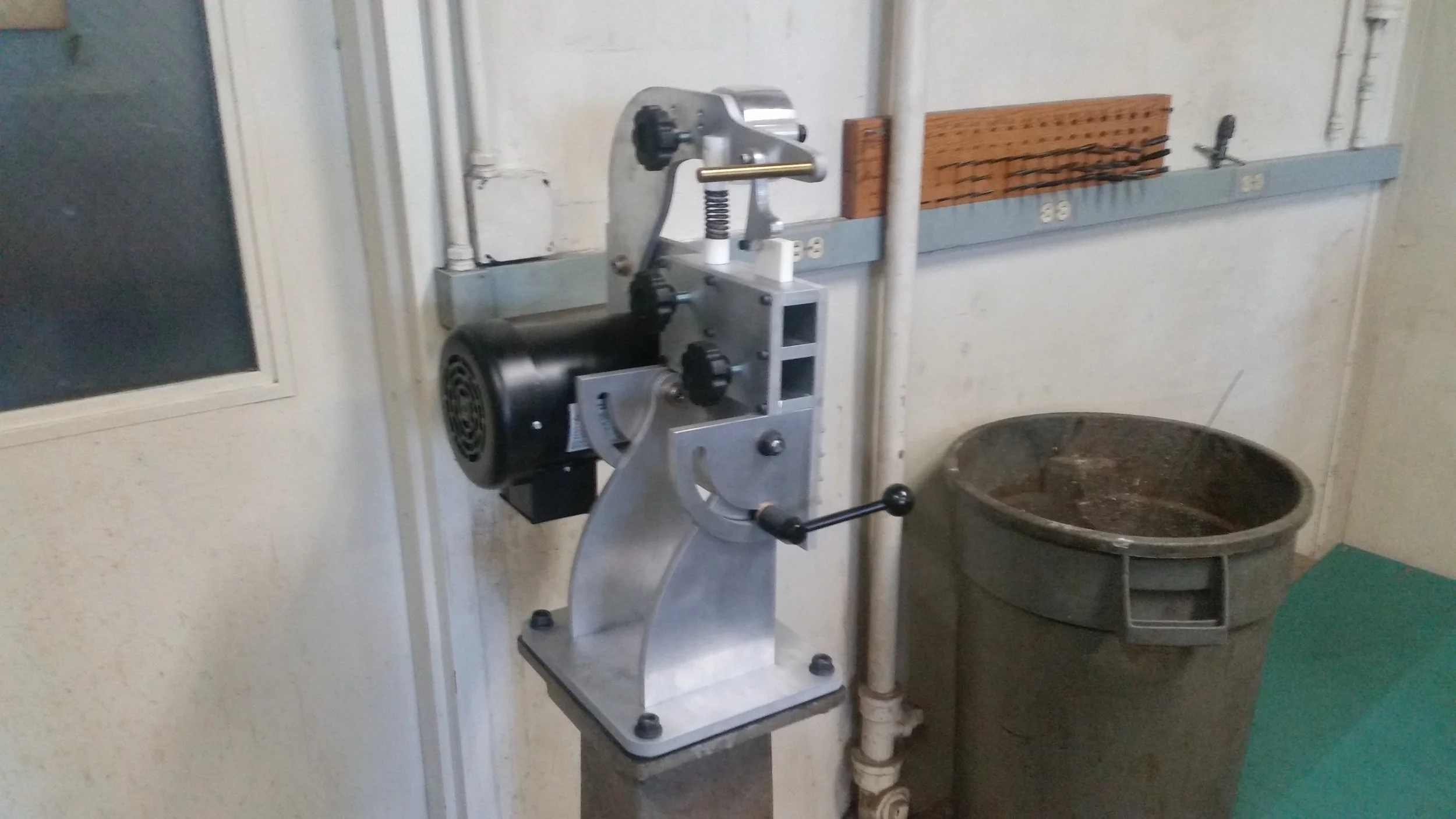
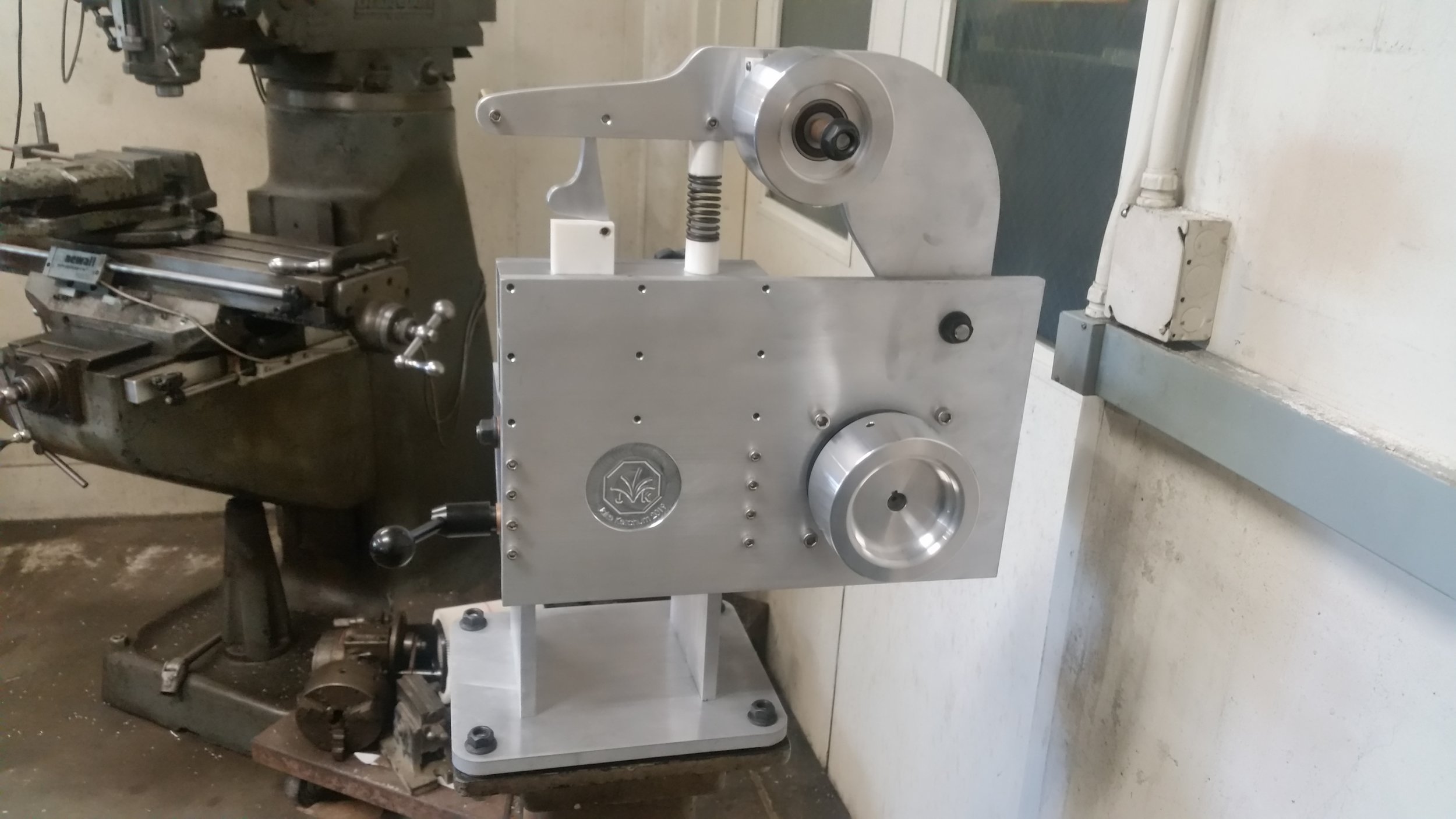
The grinder is done! I’ve got some ideas for new things to add and additional tweaks to make, but as far as the core build is concerned everything is finished, running, and ready for use.
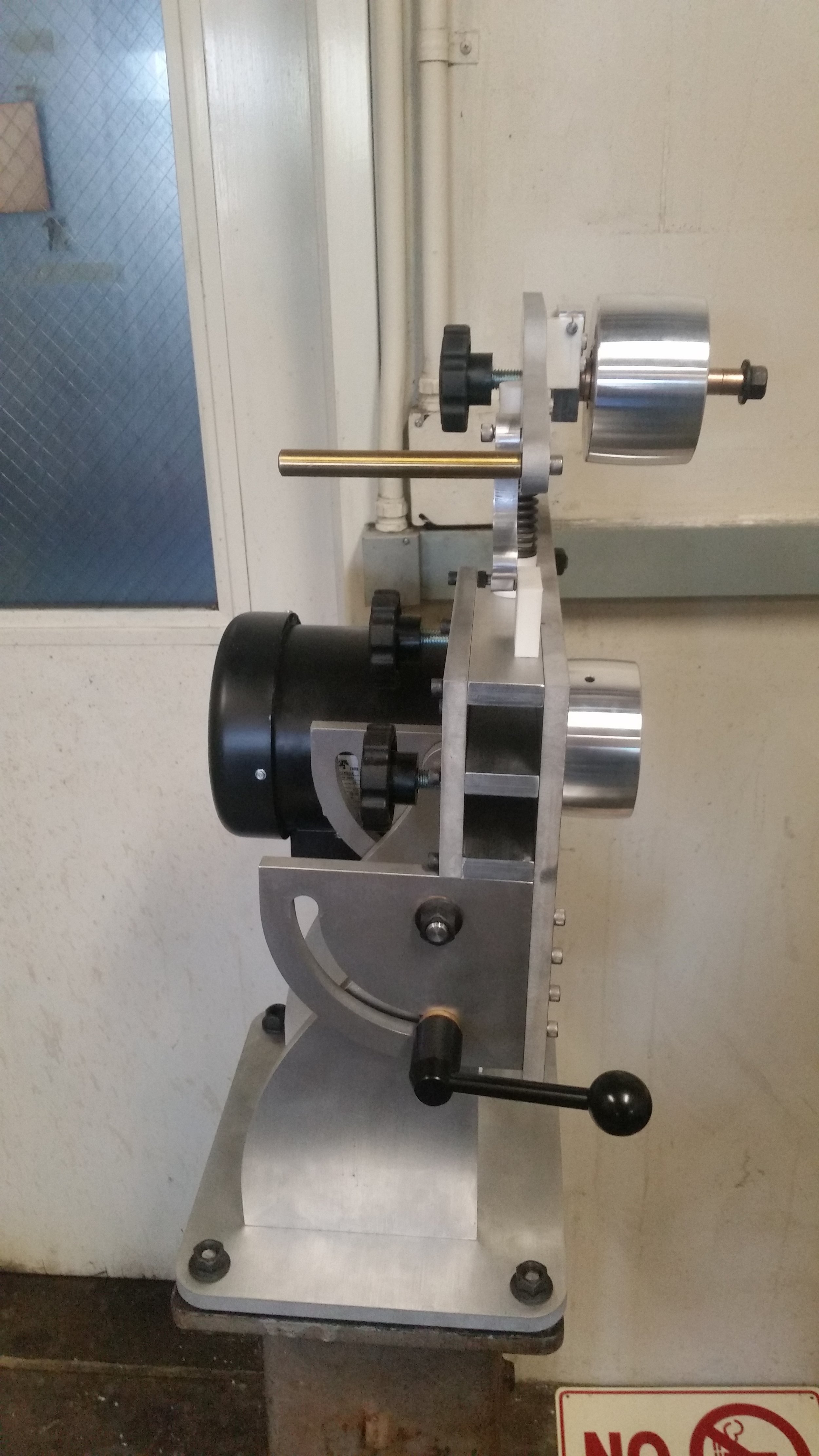
The grinder uses a 1.5hp Iron Horse connected to a 6” drive wheel. The motor is controlled using a Kbac 27-D VFD configured with variable speeds, reversing, and a momentary-start switch.
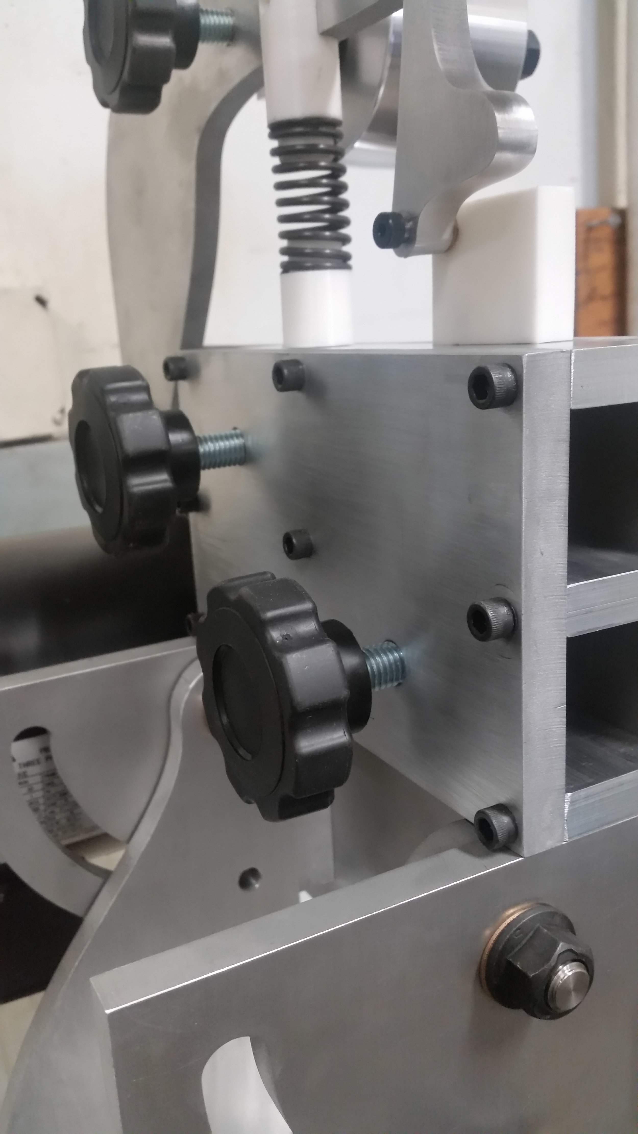
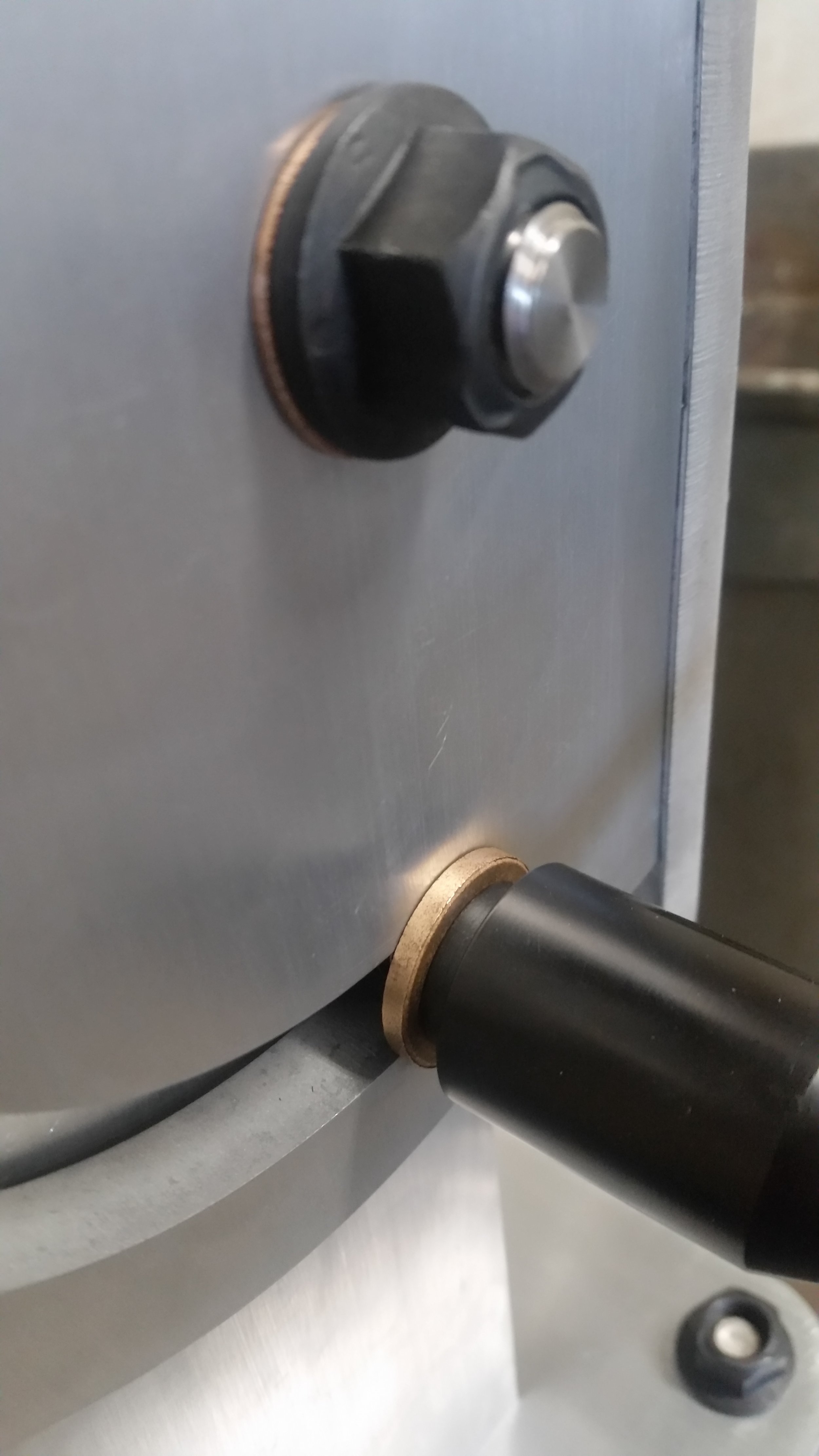
With a custom front plate the KBAC just about fits between the vertical pivot supports. I moved the controls to a separate box, mounted to the front of the grinder. The main VFD box is sealed against grinding dust with a locktite liquid gasket, and all of the cabling passes through water tight glands. The cabling is standard industrial cabling from Mccmaster Carr and is covered in replaceable cable sheaths to protect against abrasion.

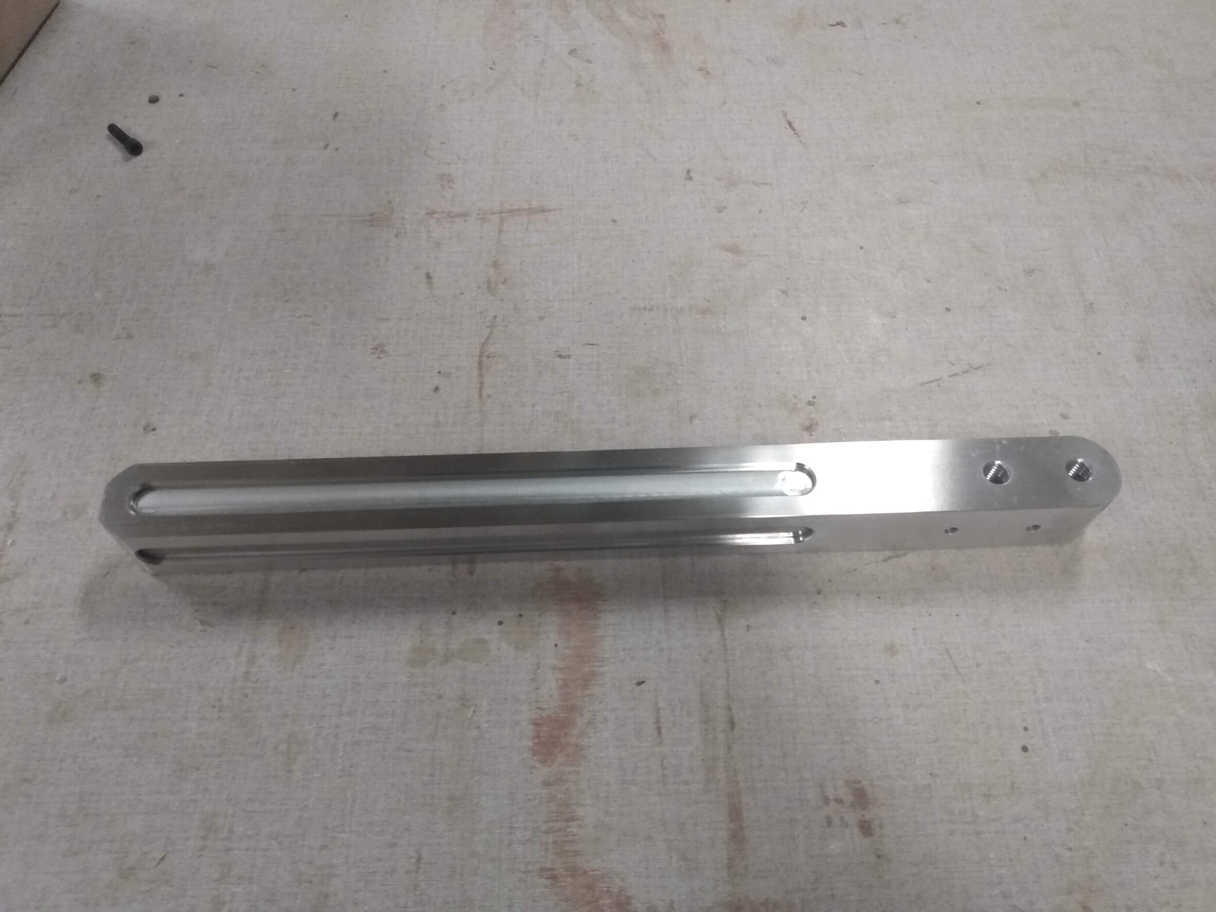
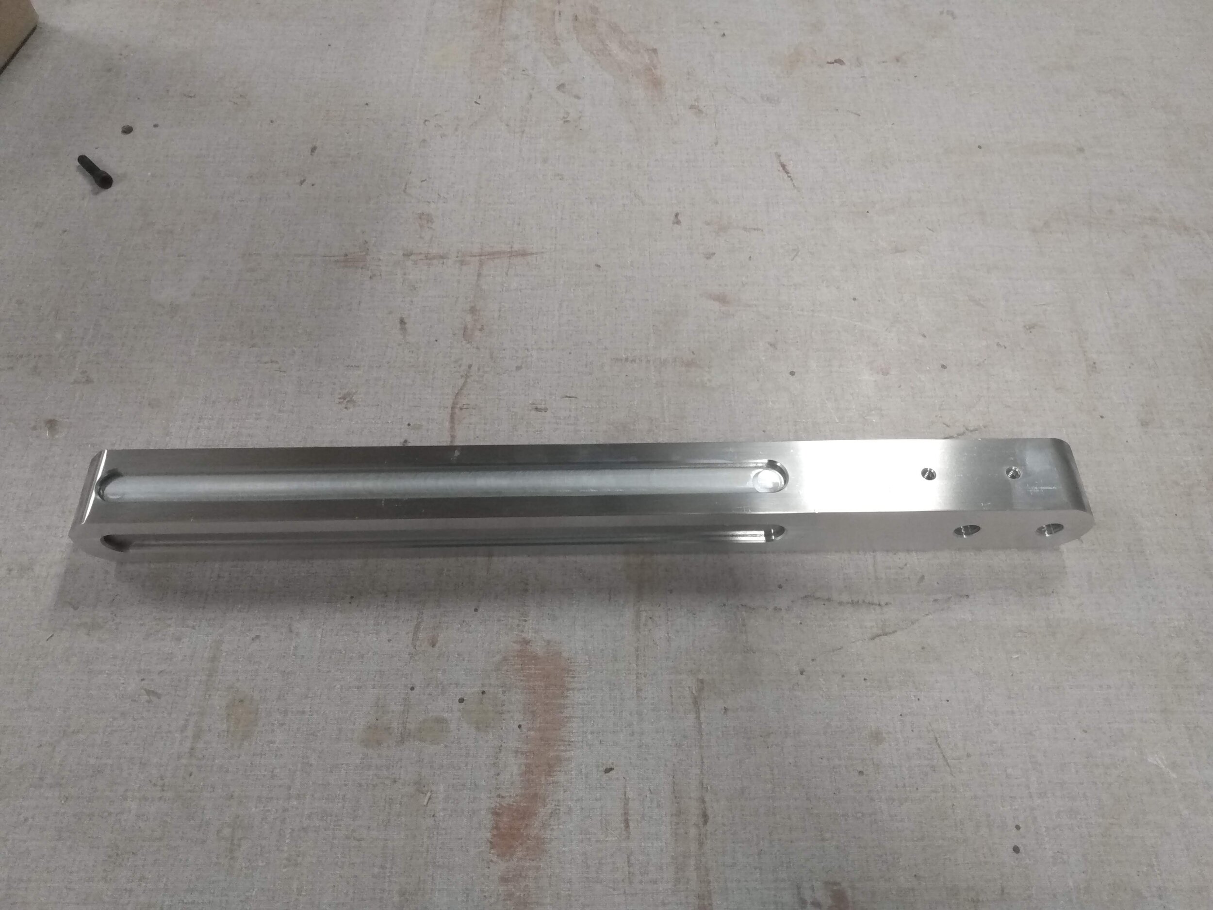
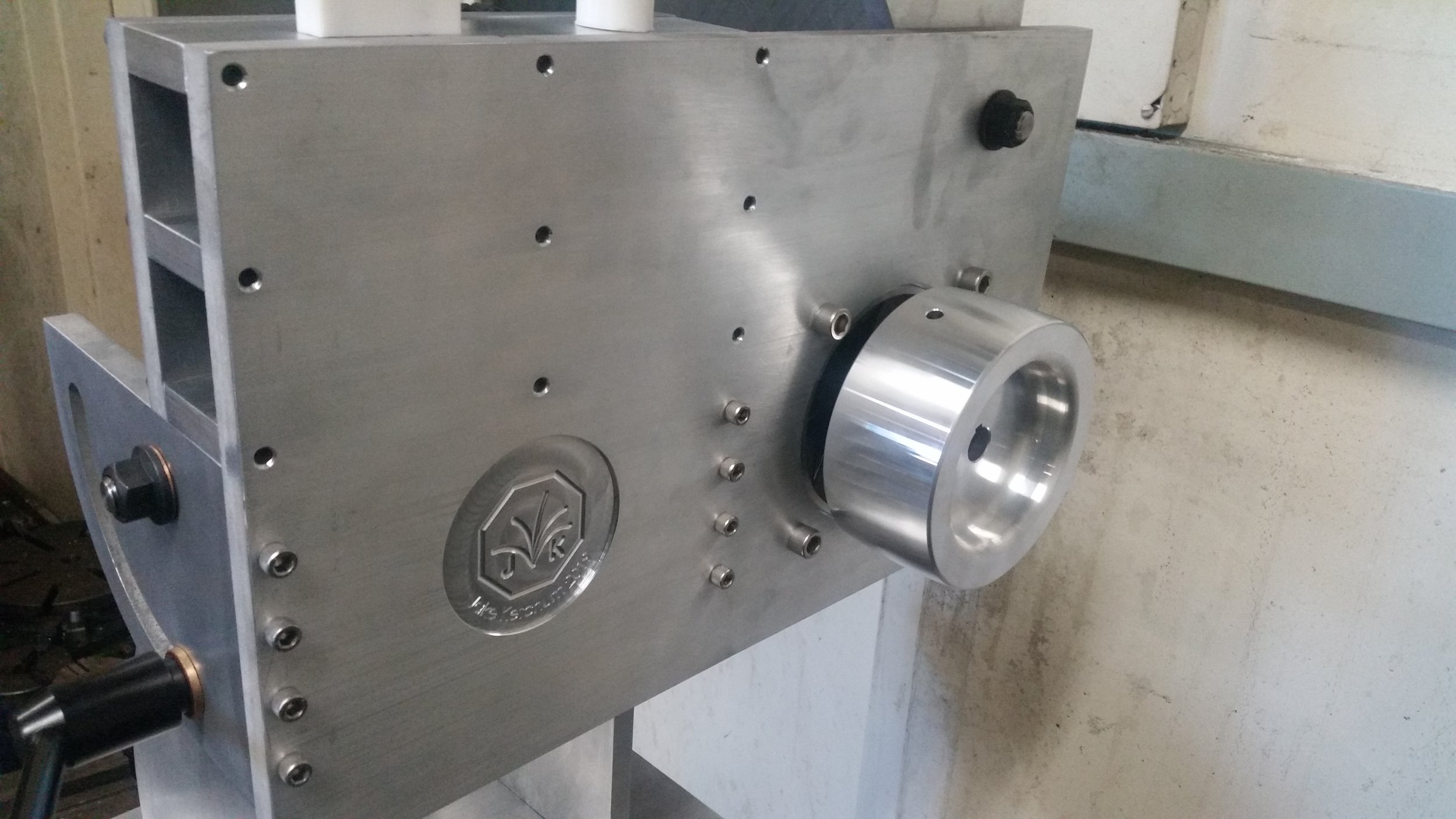
The front plate, after brushing but before installation.
VFD:
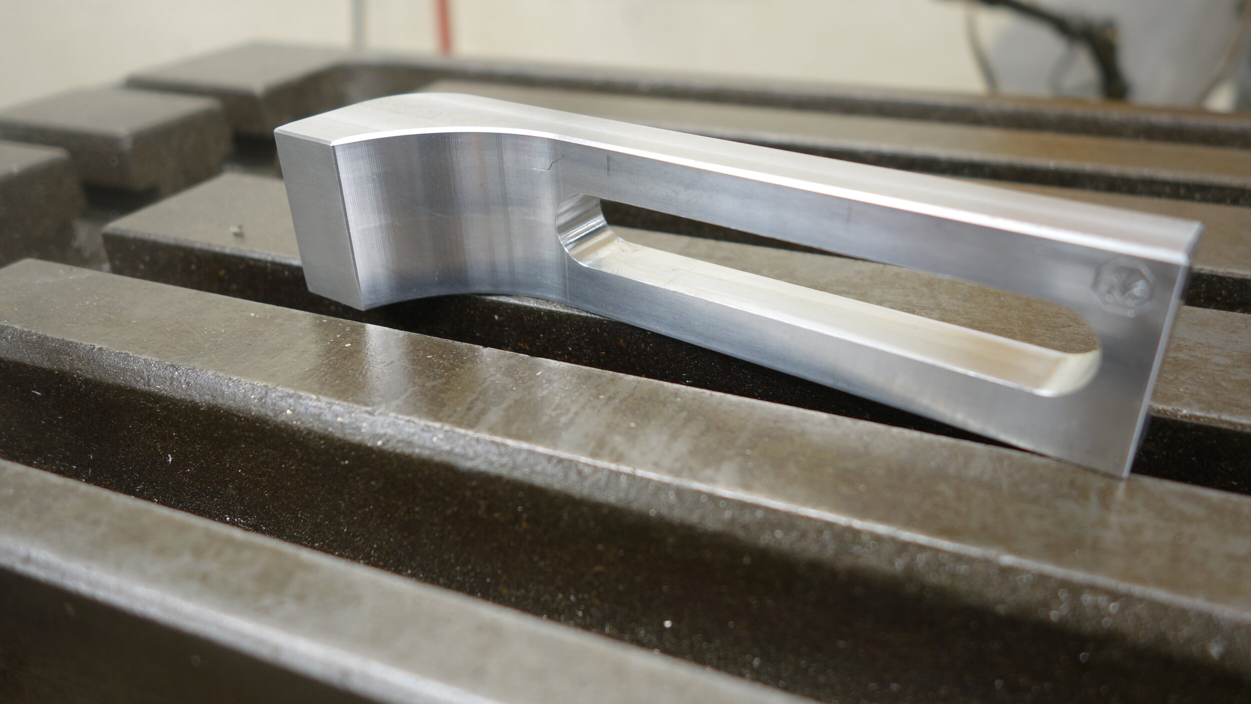
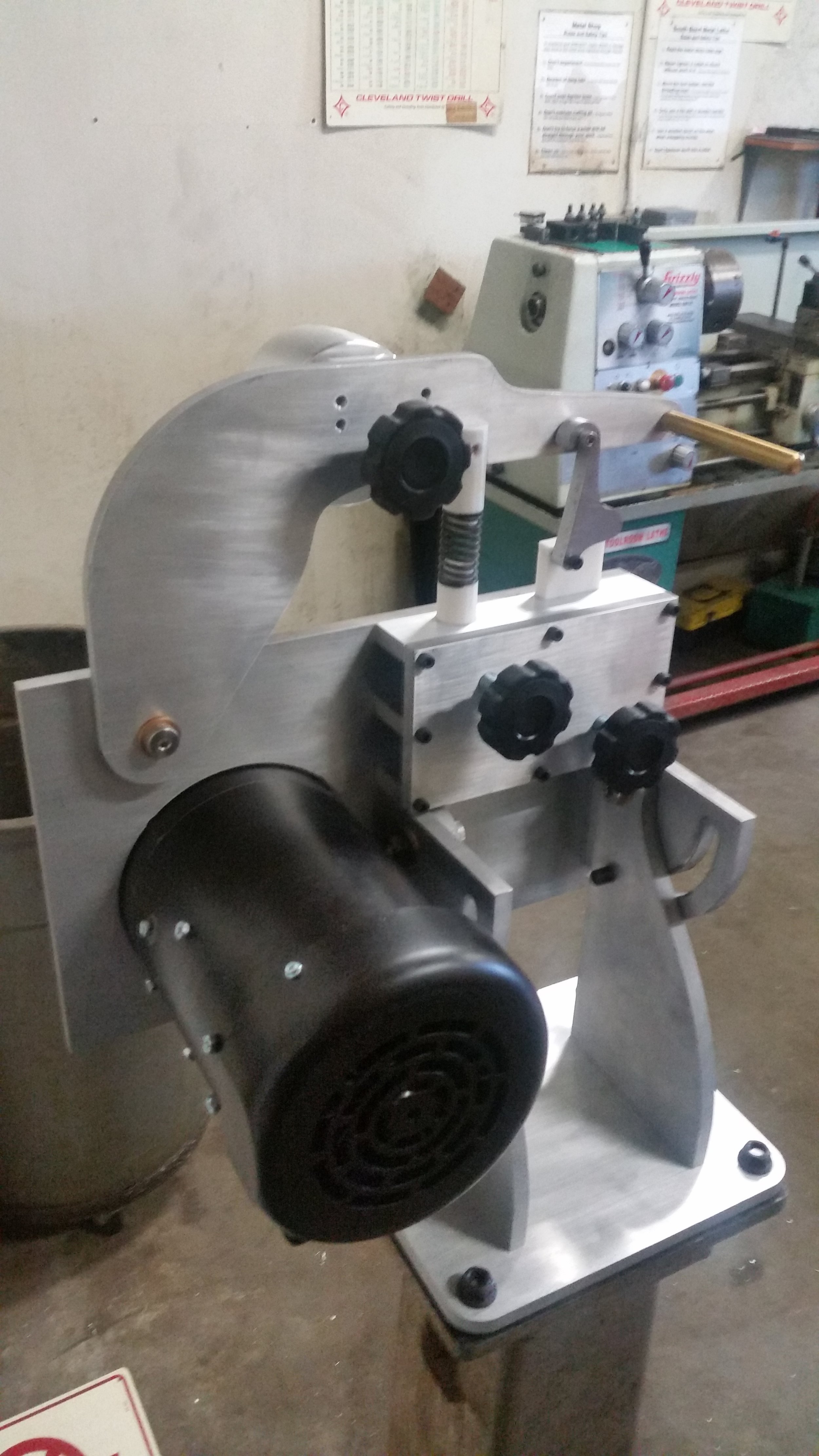
The variable frequency drive (VFD) which controls the main motor is located between the two vertical pivot arms. To accomplish this I added a horizontal bar on the rear pivot arm, and replaced the front VFD lid with a much thinner custom panel. The horizontal bar was constructed of the same 1/2 by 2 aluminum extrusion that was used for the arm plates, and the front cover was blanked out of spare 1/2 inch aluminum plate using the waterjet.
After blanking, the front plate was machined on the Haas to add the gasket groove, counter bores, and display features. I also removed most of the material from the center of the plate to provide a bit more room for internal wiring (It’s tight, but fine). One particularly fun feature of this part is the display area. I included mounting geometry for the original LED board, and turned some acrylic plugs to pass light from inside the box.


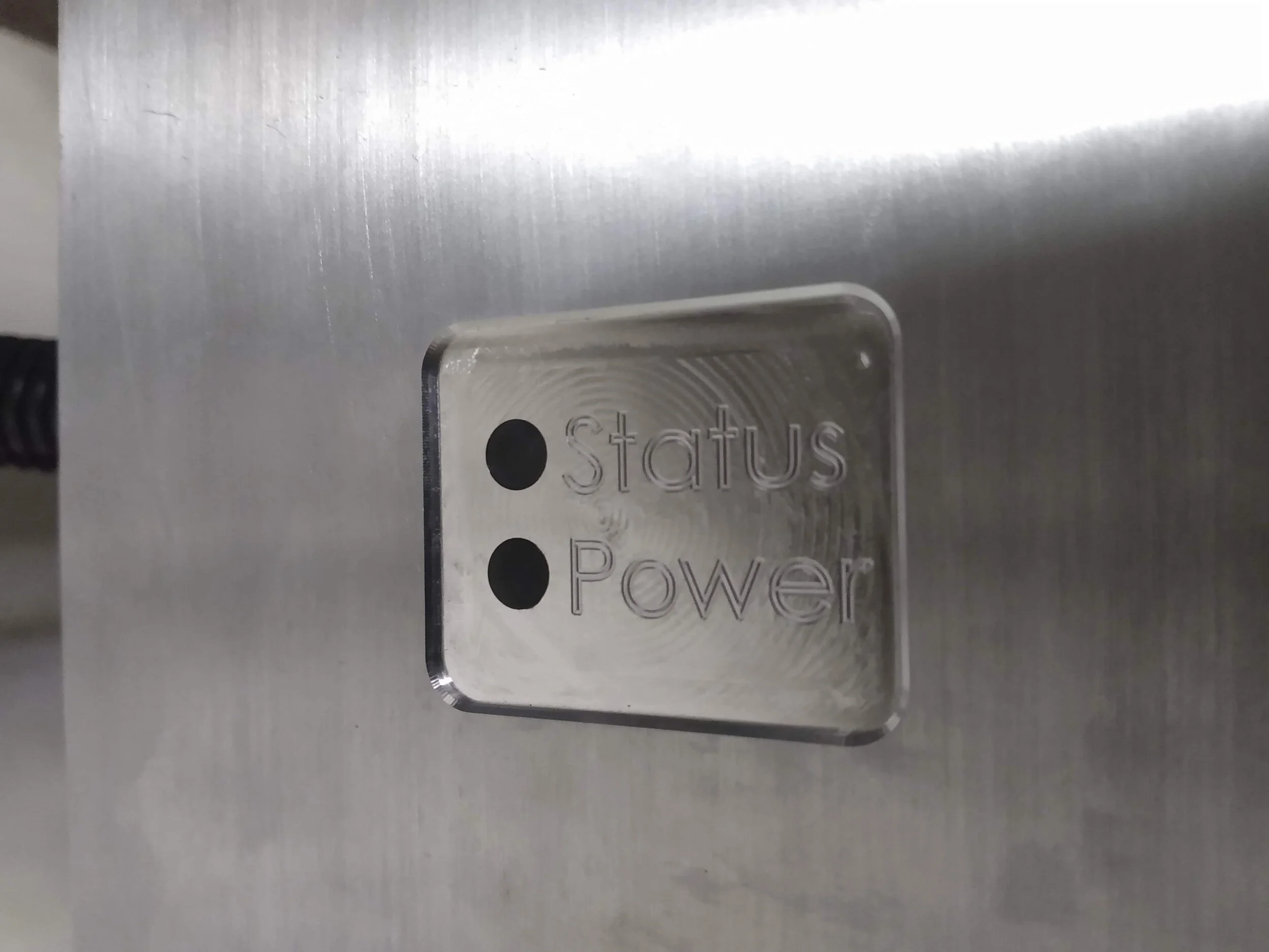


Photos really do not do the control box justice. This is one of the nicest pieces I have ever machined.
Control Box:
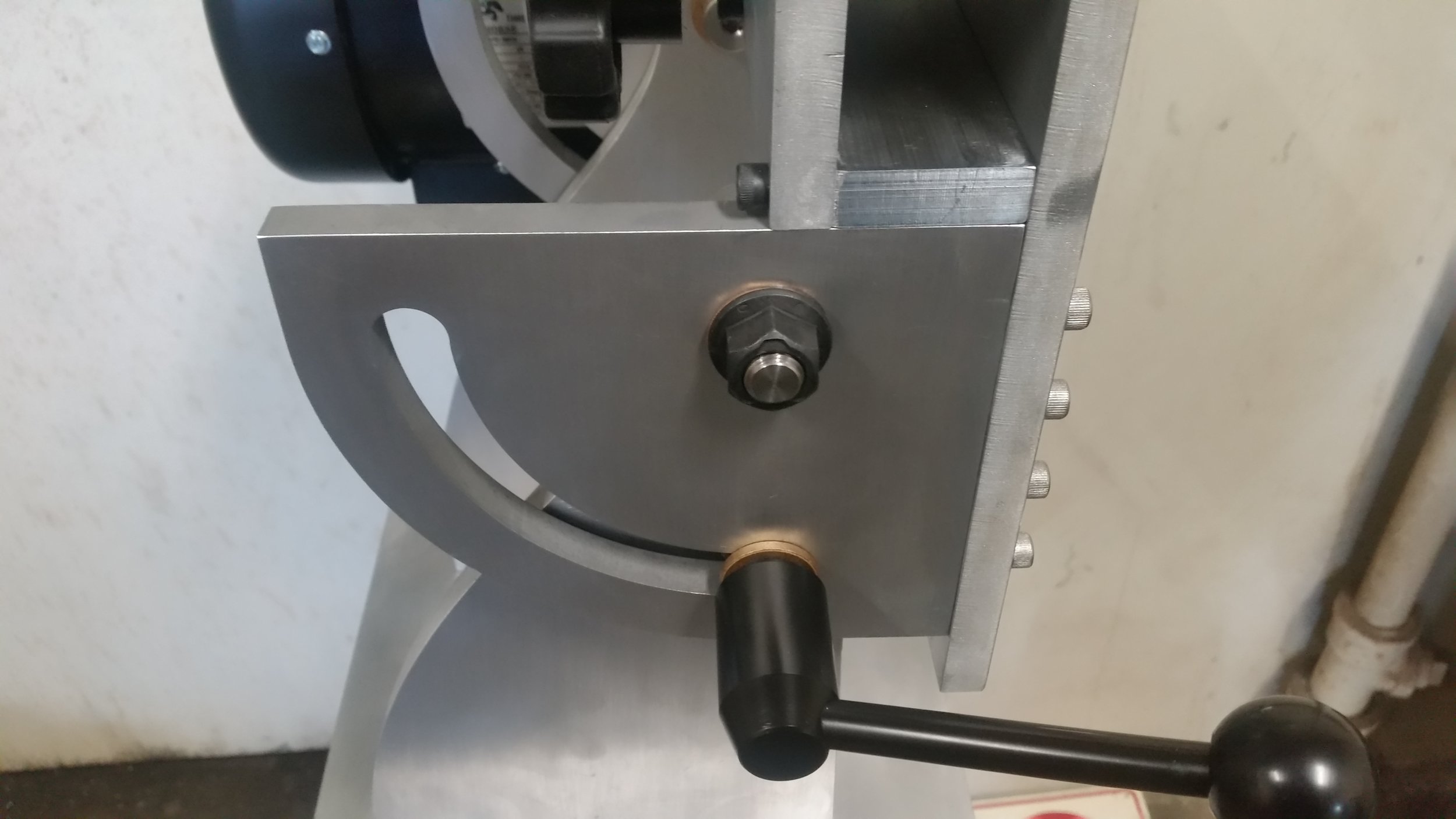
Mounting the VFD between the grinder legs means there is no way for the user to interact with its normal switches and knobs. This control box allows the speed control, direction control, and start switch to be mounted directly on the front of the grinder where they are easily accessible to the user.
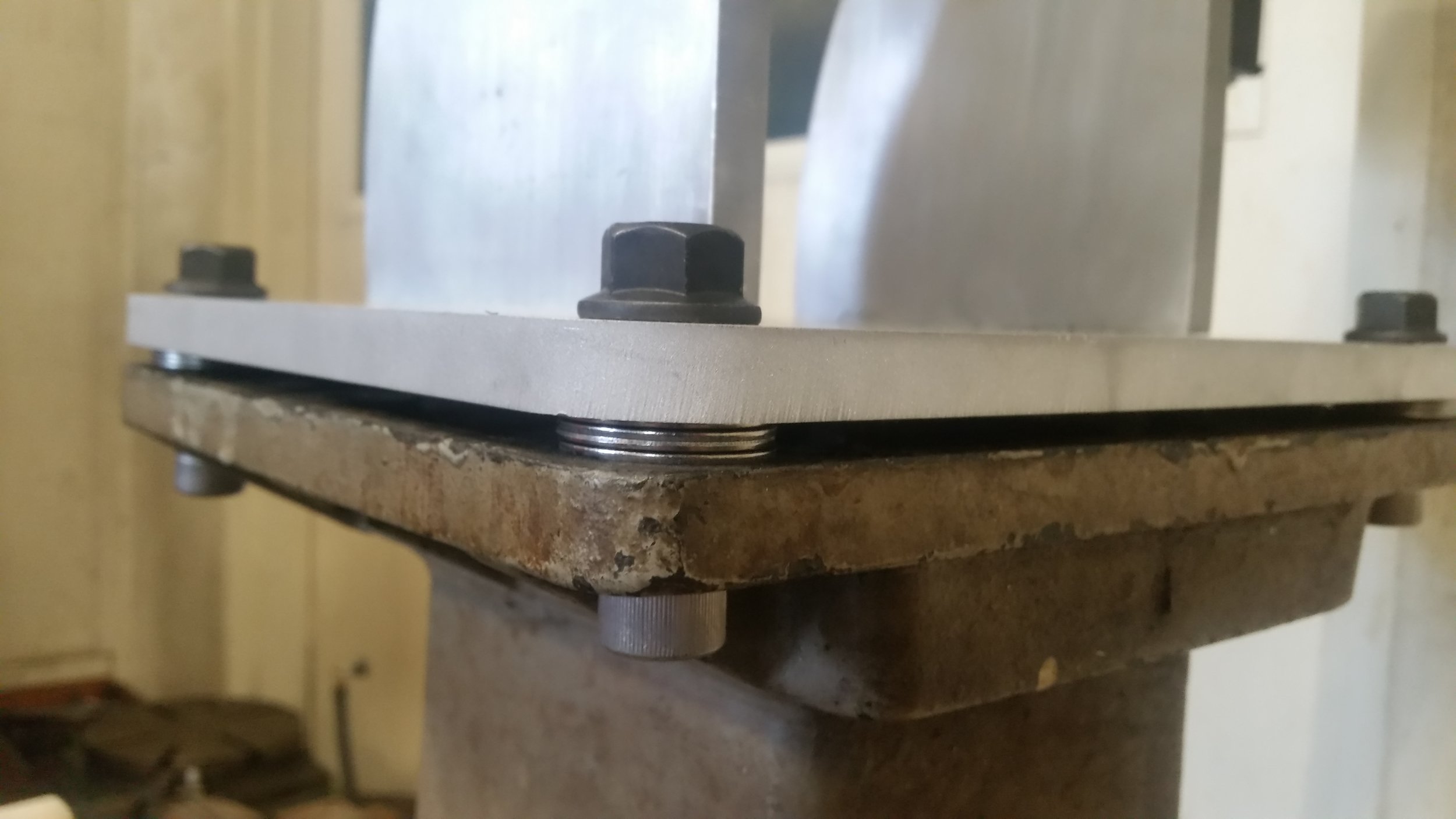
The box is machined out of a single piece of 6061 aluminum, and is mounted to the grinder by four 4-40 screws, which connect to the box’s rear cover plate. The dial design is based on cockpit of a DC10, and the engraved lines have been filled with lacquer to help them pop. All of the controls are sealed against dust, as is the gland that permits the control cable to enter.
The lacquer sticks are a new technology for me, and I was pleasantly surprised by how well it worked. Getting good results took a bit of practice, but was otherwise quite painless. The method I settled on runs as follows. First, use the sticks to cover the engraving in a thick layer of lacquer. Then, use printer paper to remove as much of it as possible, switching paper locations frequently to avoid smearing. Finally, touch up the results with printer paper soaked in IPA.