Overview:
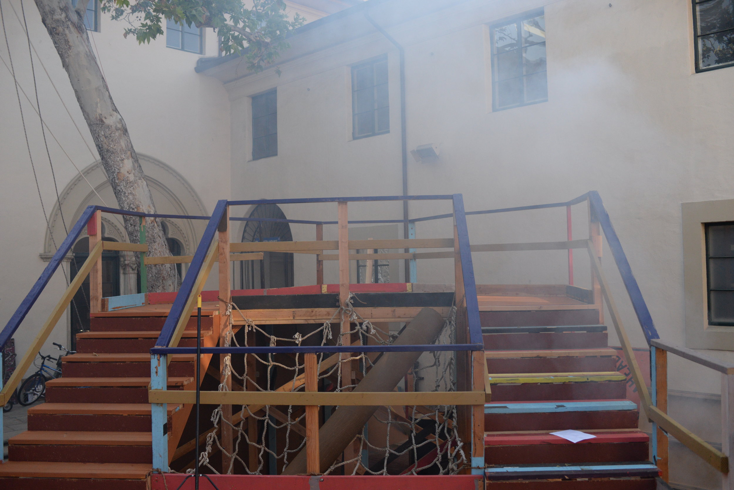
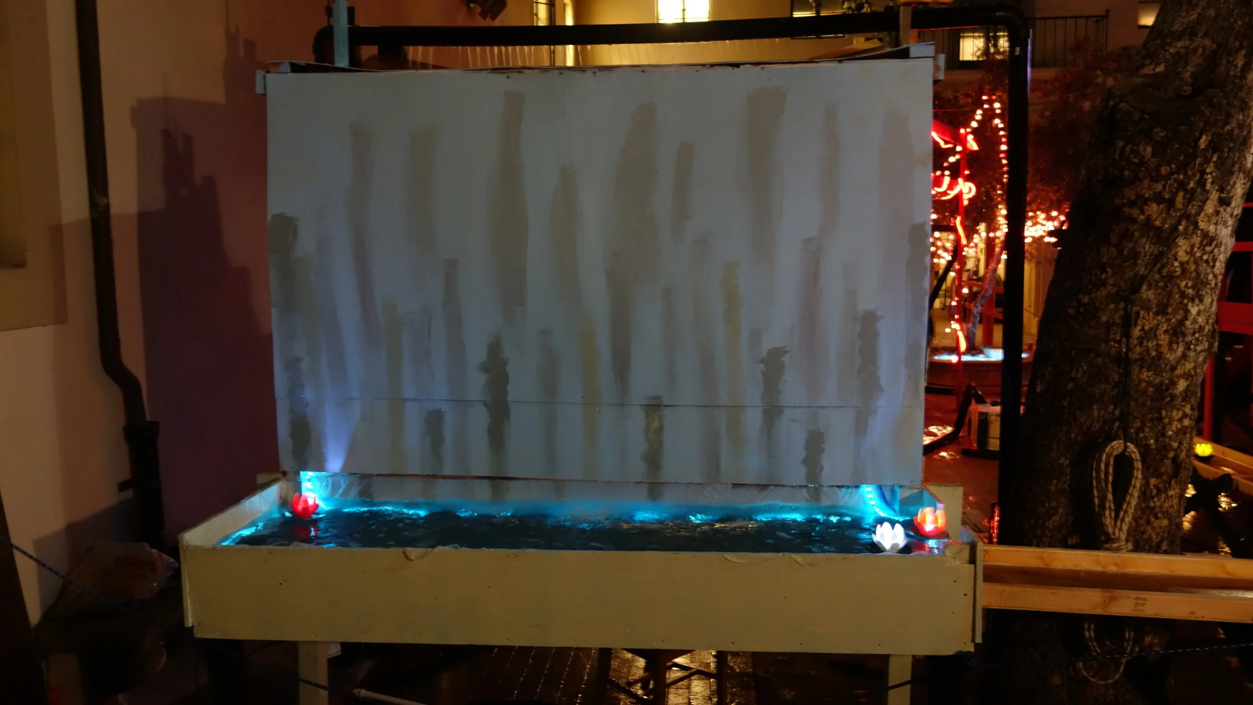
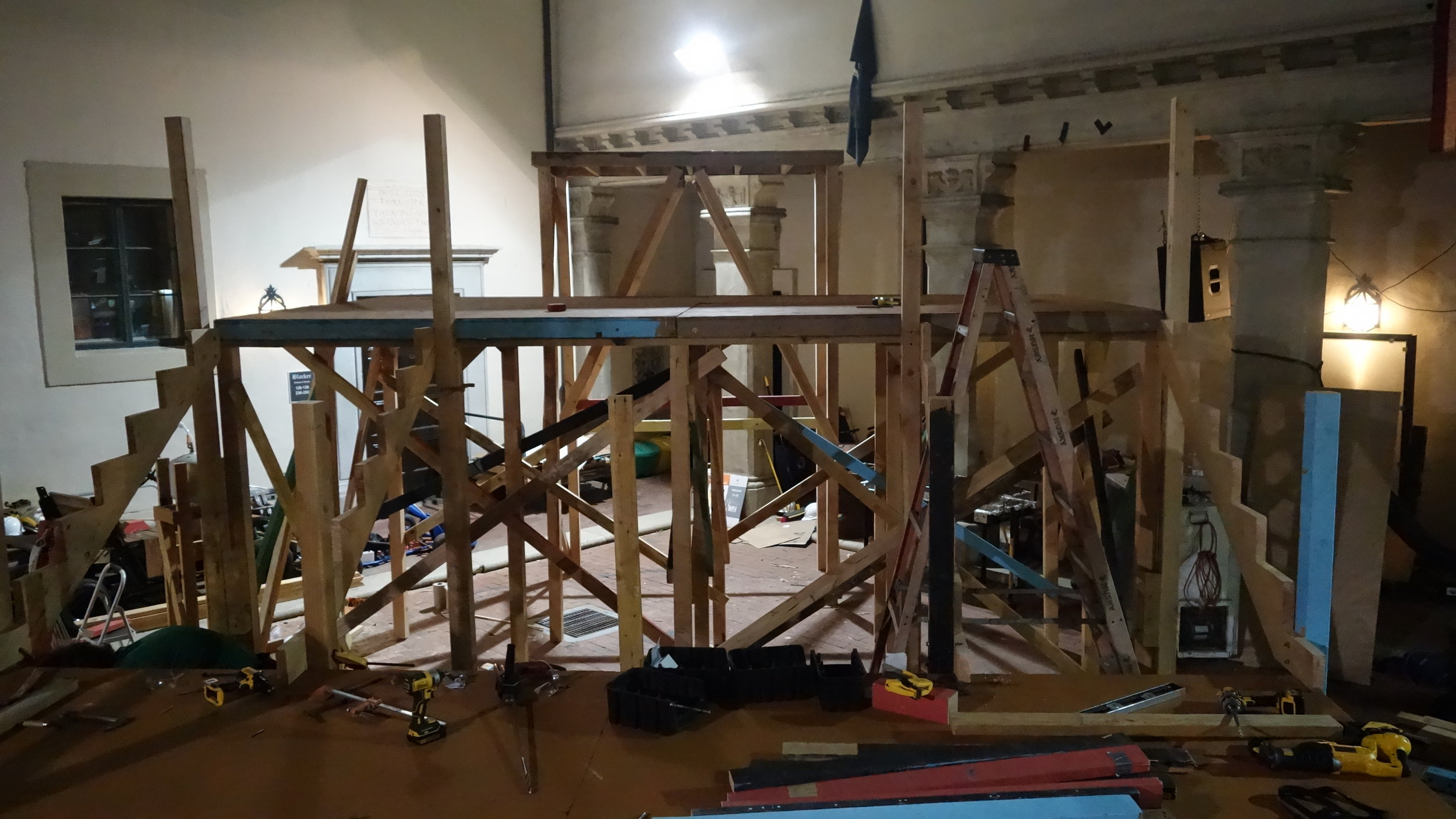
The bow stairs prior to painting. Photo credit: Ethan Jaszewski
Blacker's 2018 interhouse featured 5 staircases, all cut and assembled fresh for this year's platform. We made 48” staircases running from the lower platform to the upper platform, and one 53.75” staircase running from the ground to the lower platform. All five staircase units were structurally self-contained units, bolted onto the main platform. The 53.75" module was constructed relatively early on to aid with general platform construction and allow viewing platform access during PFW. The four 48" units, although nominally freestanding, were assembled in place so they could be adjusted to the real gap between the upper and lower platforms.
Our overall assembly time ran about 16 student-hours per unit, with efficiency peaking at three people for fabrication and four per staircase for assembly. Discounting costs associated with elevated construction, each unit had a real-world cost of 100$, with an expected amortized cost of 40$ and would have cost 150$ using all-new wood. More details about construction time and budgeting can be found below.
After helping rescue last year's debacle, my big focus this year was on establishing efficient fabrication practices, and using good documentation to parallelize construction. Although there's still a lot to work on next year, I was successful in cutting our assembly time by about 60% per staircase, while reducing the total unit cost by 30%. Having full mechanical drawings let students with a passing interest take over fabrication of a single component, and made it easier for more engaged students to get up to speed on the overall design.
My role:
I ran the project, managed the budget, procured the materials, created the cad, wrote the documentation, and oversaw the assembly. However, this is a strange project for me in that I did relatively little of the physical cutting and assembling of wood. Having a complete drawing packet meant that I could outsource most of the parts fabrication and focus on cutting stringers and teaching people how to use our tools.
General Fabrication:
With 5 staircases to produce, we focused on trying to produce as many of the parts as possible in batches. This was largely successful for the stringers, support posts, treads, and kick-plates. However, we found that irregularities in the platforms themselves necessitated custom fitting for the railings.
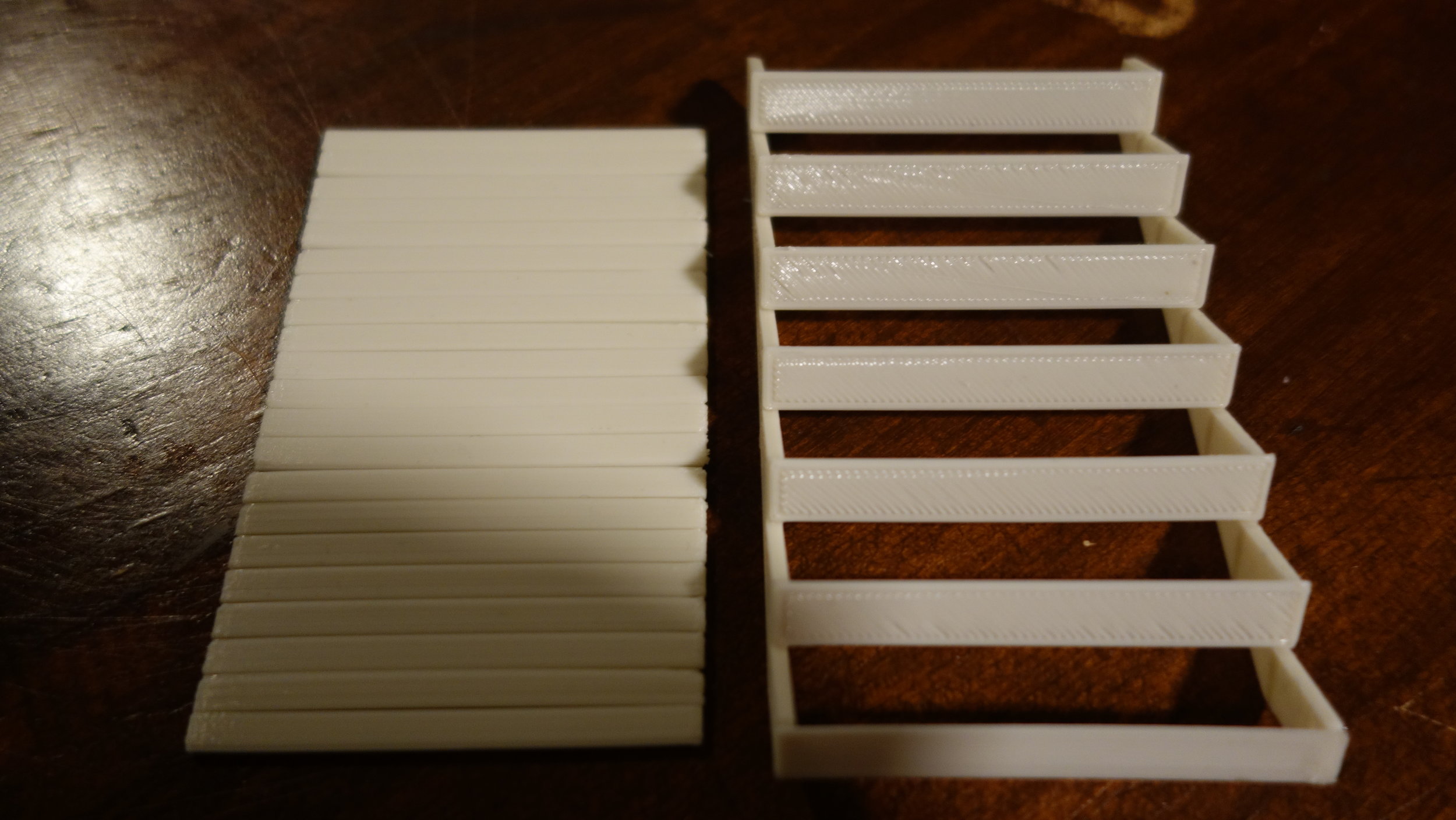
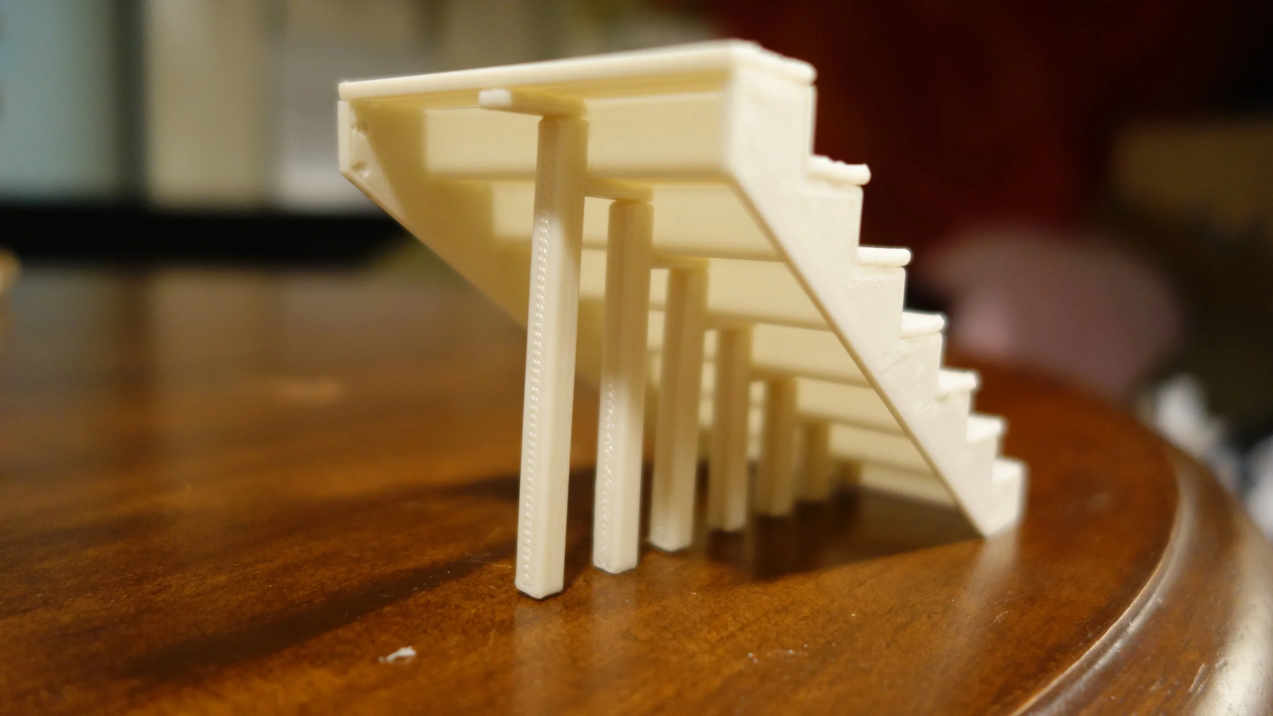
Stringers:
Stringers are always the most difficult part of a staircase to source and fabricate. Since we had fairly non-standard stair heights on this year’s interhouse I decided to fabricate the stringers from 2x12s instead of purchasing them ready-made. The appropriate mechanical drawing can be found at the end of each design packet (below). The generating cad is parametric in nature (along with the entire stairs assembly) and so easily accommodated our two different stair heights. That file can also be found below.
We experimented with two different types of stringer fabrication:
To begin with, 5 high quality stringers were fabricated as follows: a reference edge was cut onto each of several 2x12s. Then the critical points for that stringer were marked according to the drawings, and then connected to form the stair outline. The outline was then cut-out with a circular saw, placed against measured and clamped straight edges.
Once 5 high quality stringers had been fabricated, we picked the best 3 and used them as drawing templates for the remaining stringers. This removed the longest step (measuring and marking), and allowed us to quickly produce the bulk of our stringers. These stringers were cut either with clamped guides, or free-hand depending on the confidence and skill of the saw operator.
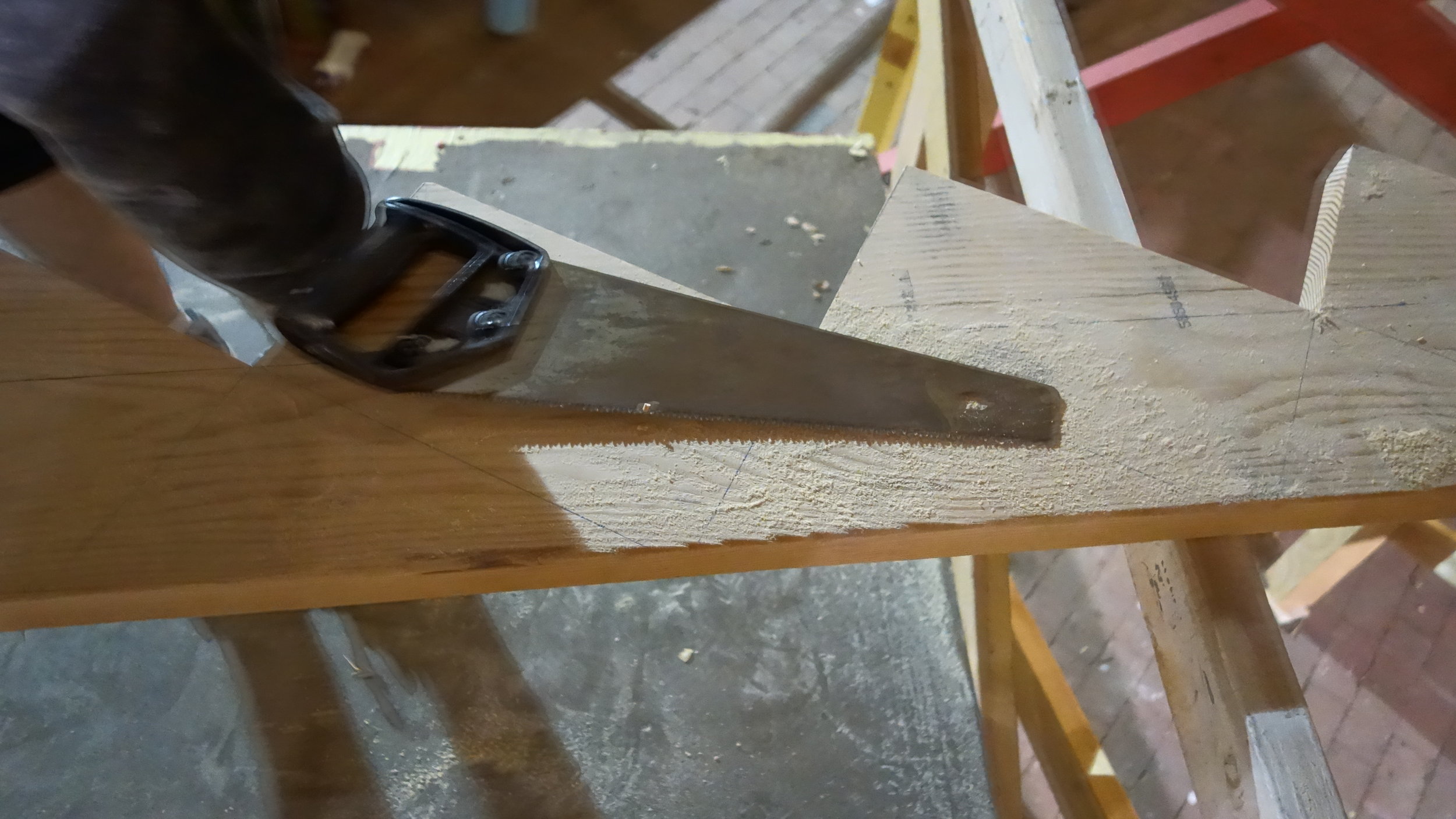
In both cases, we found it necessary to finish each cut with a hand saw, so as to ensure clean corners. This added about 5 minutes per stringer, but provided a 10% increase in strength relative to over-cutting with the circular saw. Likewise, we found that teams of 2 people were most efficient for both types of fabrication.
Reflection: Stringers cut free-hand using drawn templates were substantially less consistent than those produced directly from measurements. However, they were structurally equivalent and proved largely sufficient in practice. The 70% reduction in speed was more than worth having to throw out 2 wasted blanks.
Assembly:
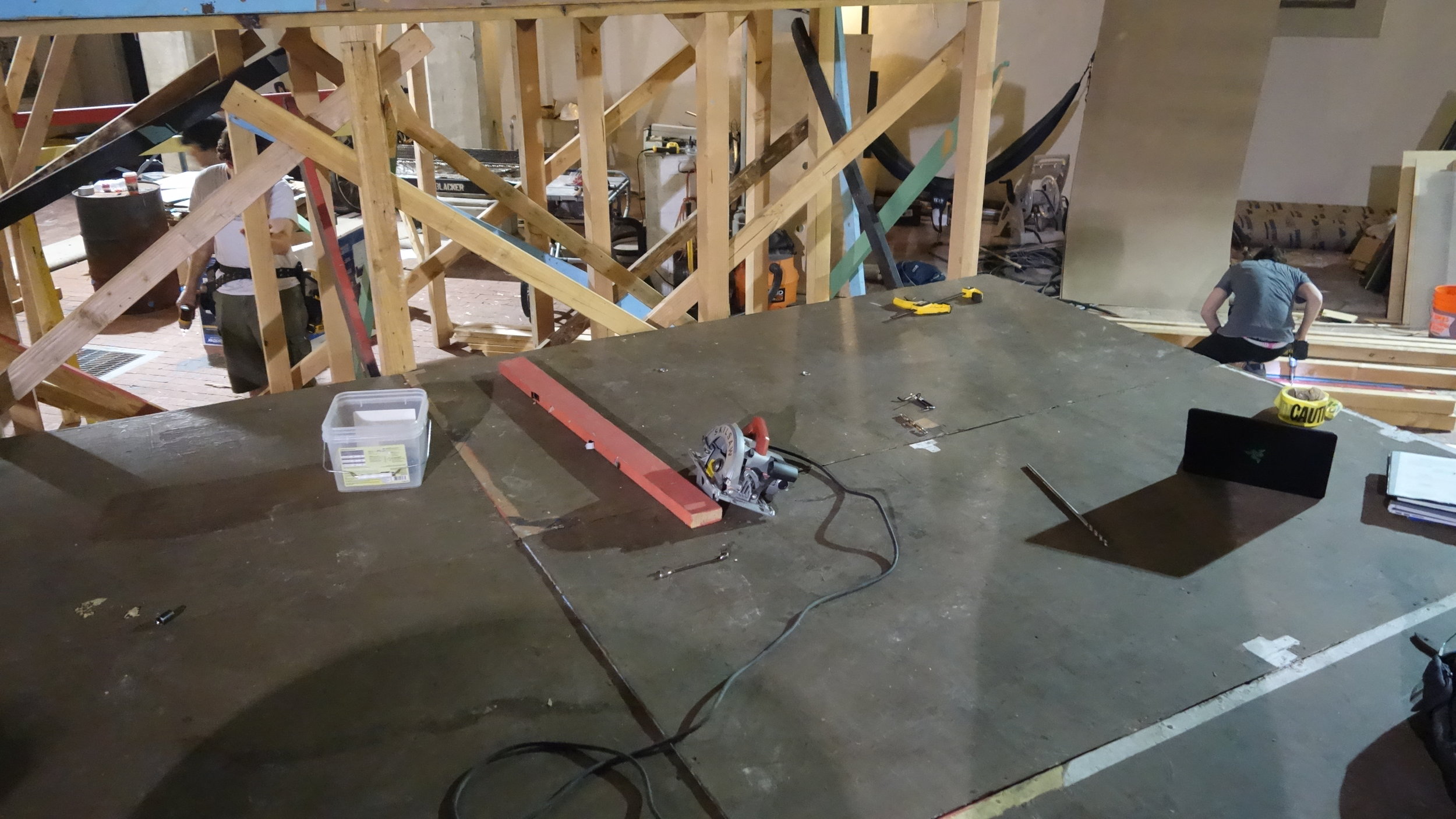
Assembly went very well this year overall. I was able to train both our work-frosh to manage assembly groups. This fread me up to do the safety checks and help out where needed. We were generally able to keep two groups working at a time, and were largely limited by our clamp supply more than people or materials. The general process we used ran as follows:
Place, clamp, and bolt vertical alignment posts. Where possible these were bolted directly to the main platform supports with 1/2" bolts, but in some cases we used an additional 4x4 to act as an intermediary so the stair supports and platform supports could be placed corner to corner.
Clamp both outer stringers and drill the stringer to post bolt holes. Note: In the future I would recommend creating a drilling jig for this process. It was difficult for some participants to remember that consistent drilling is important for re-use.
Place the central stringer, and connect it with treads at the top and bottom of the stairs.
Continue up the stairs from bottom to top, placing treads. We used three 2x4 treads per stair, with all three pressed towards the outside of each stair. This left no gaps between treads, but a significant gap between the kickplate and treads. It was determined that this was better for students wearing heals.
Once the treads were all placed, they were then screwed down. We found this to be most efficient with two people (one per side).
This process was then repeated for the kickplates, placing them with the gap towards the top of the kickplate.
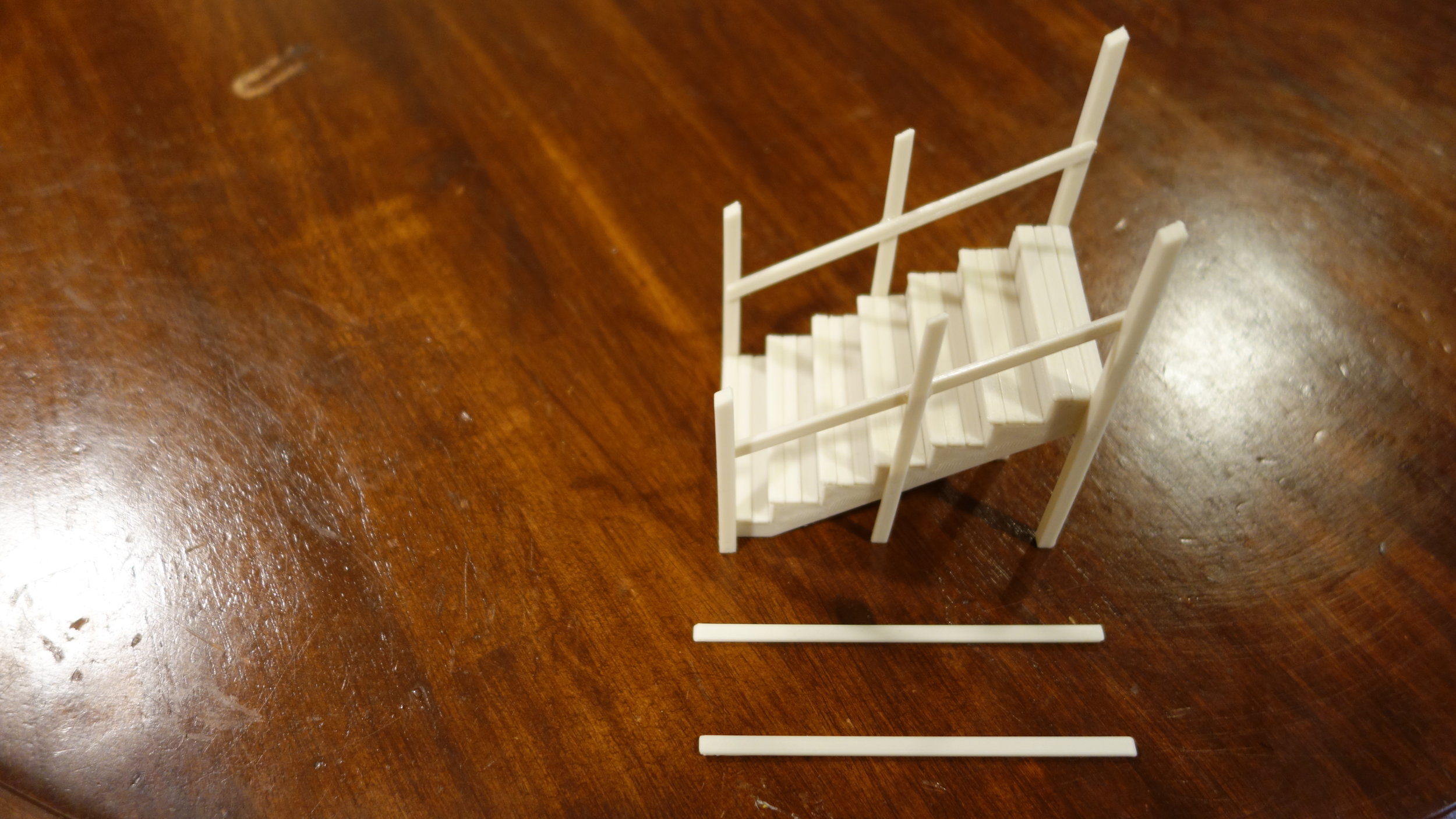
Finally, railings and railing supports were added. We cut these parts beforehand according to the CADs, but ended up needing to make some slight adjustments to account for the placement of the dance platforms.
Recommendation: Purchase an additional six 18" fast acting clamps before next year's interhouse season begins.
Documentation:
Mechanical Drawings (Short Stairs)
Mechanical Drawings (Tall Stairs)