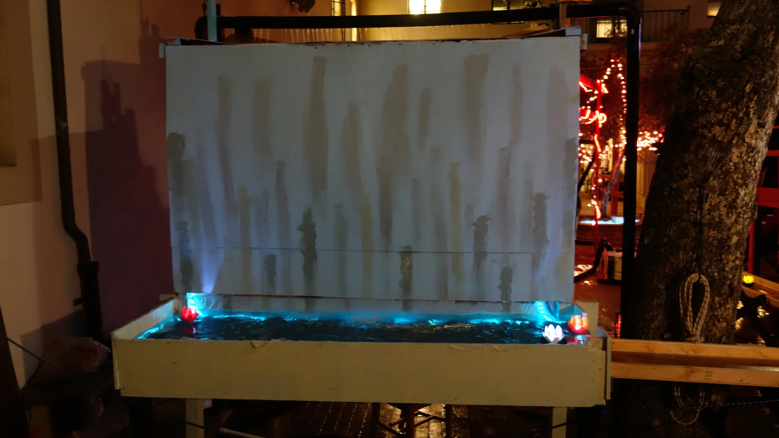
The arches as viewed from the dance platform. You can see where the inner illumination hits the stream breakup right before the arch.
Summary:
This post covers the design and construction of two laminar flow nozzles with LED lighting. The two units have a throw of around 10’ and, with the exception of our outlets, are made from materials that can be easily sourced at home-depot and an aquarium store of your choice.
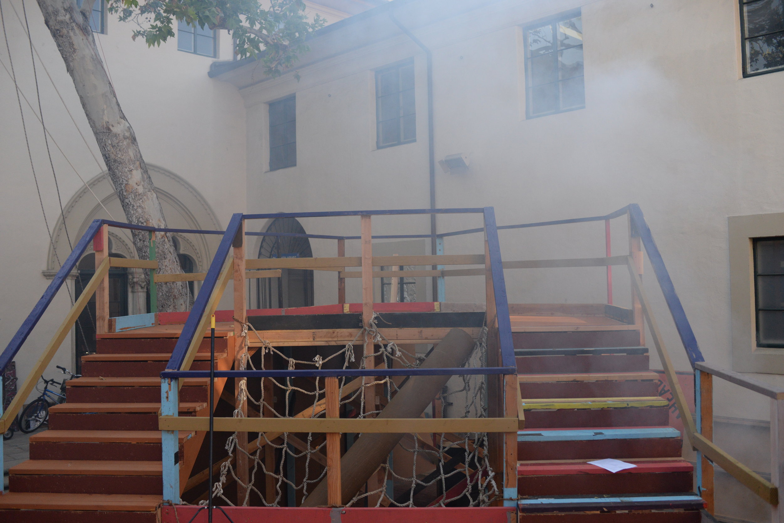
This was my 2019 interhouse* project, which I co-lead with Jack Caldwell. The overall theme of the party was “bio-luminescent world” so the two nozzles were installed with RGB LEDs over the entry bridge to Blacker’s dance platform. Overall, the fountains seemed to be very well received. Early on in the party they were a popular photo spot, and people were playing with one or both of them pretty much constantly throughout the party (see the video for what that looked like).
Collaborators:
The best part of any interhouse is always getting to work with other moles on a project of mutual interest. I was delighted to work with the following fellow students.
Jack Caldwell (co-lead)
Brittany Wylie
Harrel Dor
Gracie Suenram
*An annual event which, in Blacker, falls somewhere between a party and a tech-demo.

Outlet:
The outlet of a laminar flow fountain is a bit odd. Since the goal is to minimize turbulence, you actually want to design it with the cleanest, roundest, sharpest inlet edge possible. Then you want the rest of the nozzle designed such that the water doesn’t touch the walls (frequently this results in a sort of inverted cone geometry).

We went through a number of designs before ultimately settling on CNC machined inserts set into 3D printed inserts. The large outlet cap for our nozzle holder takes 12 hours to print, so using a modular design helped us keep the printing time per test down to a much more reasonable 1.5hrs per part. Both the nozzle holders and outlet caps were 3D printed on either the school printers or my own machine. To help with waterproofing, I increased the floor, wall, and scieling thickness to 1.8mm, and upped the infil to 95%. We also found that using 3D infills (any of the ones based around printing cells) worked better than 2D infills, though the difference was not substantial. Some of our rushed 3D prints did leak, but the ones we printed on-spec and on-speed never leaked. The parts were sealed against each other using marine grease for testing (which sort of worked) and using super glue for the final fitup (which also sort of worked, but didn’t require clamps). We used 4-40 threaded inserts for the outlet cap to nozzle holder interface.
Note: Our first quick-swap system used a female threaded pipe cap, and 3d printed threaded inserts. This may or may not have been sufficient, but we moved away from it out of a concern that the threads were disrupting flow and limiting our performance.
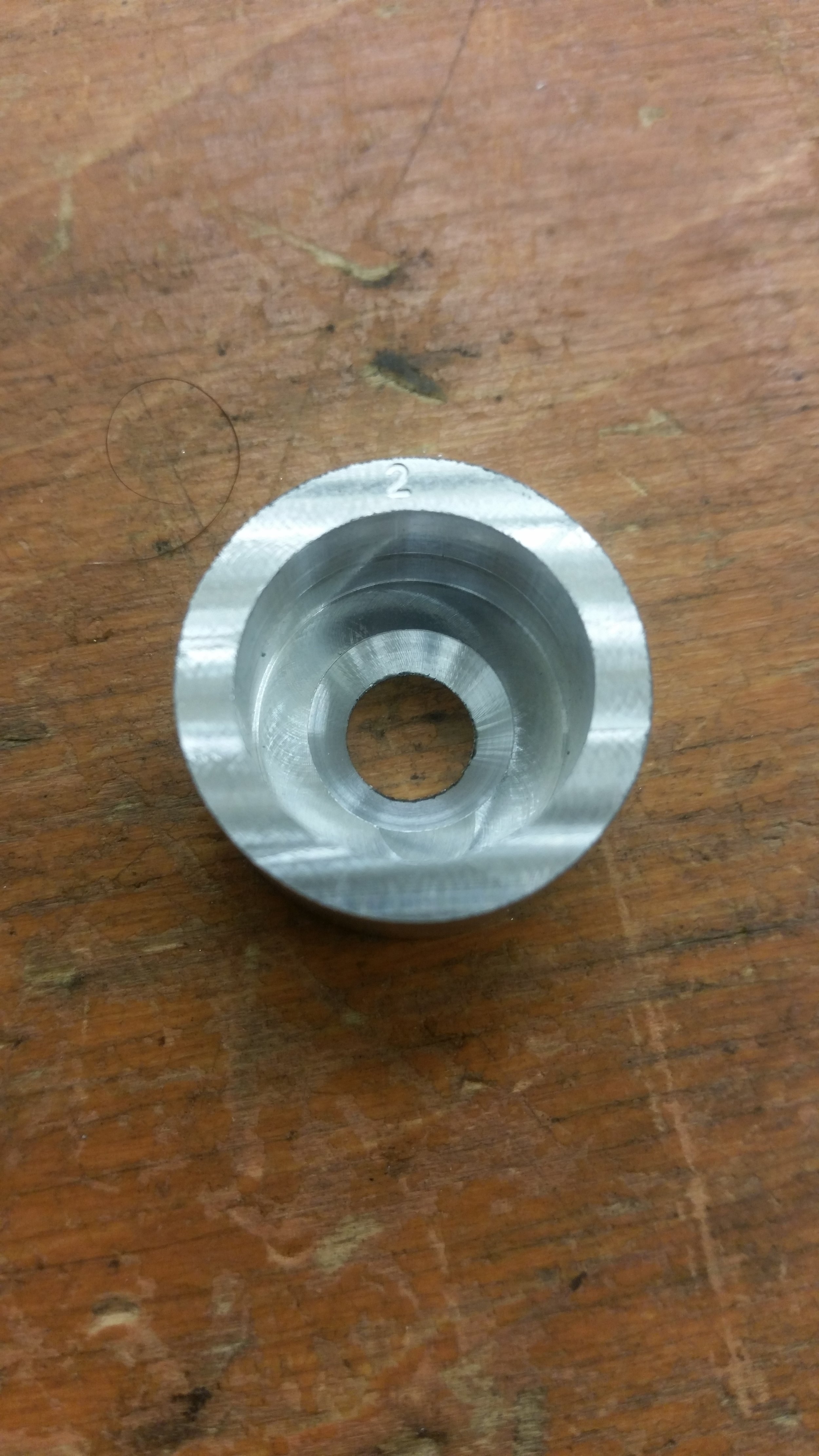
The actual nozzles were cut on our Fadal VMC15 out of 1” aluminum stock. The central hole was bored to 5/16 using a 1/4in carbide endmill, and the counterbore was bored to 3/4” with the same endmill to prevent the stream from contacting the walls. On some of the nozzles the outlet hole was then counterbored to reduce the walls to a sharp point, while on others they were left at their full 0.1” length. The water seems to neck sufficiently to avoid the full 0.1” nozzle length and thus both geometries performed equally well. In the hope that it would produce a better edge (which under a microscope it certainly did) we lapped two of our 3 nozzles. However, while this did improve the edge it did not improve performance so it may be that we were limited in other areas.
Note: I am happy with the final performance of our nozzles, and would use design #1 (short bored section followed by a 45 degree chamfer to a much larger bored section) again without reservation. However, we also found that lapped washers performed similarly as long as they were both ID and surface lapped. This may be a more economical option for you if you are trying this project without access to a machine shop. A list of the other things we tried can be found below:
Nozzle Methods Tried:

Each Nozzle was turned from round stock to (very) rough dimension. The lathe-faced side was then placed face down (see above) with a single parallel under the part for reference. The setup was then tightened and the parallel was removed. I found this setup to be sufficient for our purposes, and plan to use it for future insert cuts.
3D printed: This actually produced a great nozzle for almost all of the circumference of the anulus. Unfortunately, we were never able to get rid of the blob when the printer transitioned from the innermost line to the one just outside of it. As a result, performance deteriorated quickly past a 2’ throw*.
Laser Cut: Worked Spectacularly worse than the 3D printed nozzles, it seems the laser cutter introduced a small burr on the bottom side of the cut. After polishing that off it did work better than the 3D printed nozzles and could be promising long term. The process was very fiddly though so we moved on in the hopes of finding a more repeatable option.
Drilled Acrylic: Worse than the laser cut acrylic in every way. I would not try this again, a Delrin or HDPE sheet might work better though.
Unprocessed Washer**: This was our first strong performer. Flow remained laminar out to about 4’ - 5’ depending on the washer. Though there were some washers where it broke up immediately, so it’s important to insped each washer before use.
Lapped Washer: Lapping the washers on a flat surface and then ID lapping them significantly improved the consistency of our results. This is where we started to become limited by other factors in system rather than the nozzle. I would personally suggest going with this option unless you have easy access to a CNC mill or CNC lathe. It is however, fairly time intensive because a lot of material had to come off to get flat parts.
CNC Machined: Performed slightly better than the washers, and were much faster to make. We turned the blanks on a lathe out of 1” aluminium rod stock and then processed the actual nozzle geometry on our VMC15. Lapping the inlet surface improved surface quality, but not in a way that seemed to matter.
*all ranges given at roughly 45 degrees of elevation.
** None of our washers were stainless. This was fine for testing, but I’d strongly suggest getting a stainless washer if you want more than about 20 minutes of run time.
INLET:
We designed our inlets to generate a rotating flow in the first chamber of the nozzles. The idea was that this would better spread the water over the whole inside of the nozzle rather than concentrating it in one area. It also allowed us to print our inlets with a small cylindrical body in the center to hold the acrylic rod and LED. The inlets were printed as a single piece and took about 16 hours each. On the whole they worked fairly well, although I think some kind of self-contained tightening system to tension against the outlet caps would have helped during the prototyping phase.
In the interests of full disclosure I should probably note that this is one of the areas where we did the smallest amount of experimenting. We tried axial flow early on, but switched to radial based on the internet consensus and then never really tweaked the design. We got good dividends from the areas where we choose to focus our efforts, but I think the inlet would be a good area for experimentation on future builds.
Flow Straightening:

The flow straightener without optical bypass. I think the rough top screen and straw twist contributed to the poor performance of this unit. With that said, resolving those issues only marginally improved overall laminar throw.
The design we settled on was two pair of 2in disks of aquarium foam spaced by 5.5in and set about 1.5in back from the outlet. We sank, by far, the majority of our prototyping time into the flow straightening system, but I think it remains our biggest area of potential improvement.
In particular, most of the high performance systems we have seen online use straws, or some kind of straw analogue, to artificially lower the renynolds number in the pipe and create laminar flow. We originally started out using straws, and tried a number of different sizes and lengths of straws over the course of our build. Overall, we found that smaller and more consistent lengths, perform better than longer, or less consistent lengths. However, the effect was pretty small (though any straws performed better than no straws).
One possible reason for our poor performance could be our use of a “straw carrier”. These were 3D printed housings that allowed the straws to be packed externally and then inserted into the pipe as a unit. From a fabrication standpoint this was great, but it is possible that the irregular patterns designed into our straw carriers contributed turbulence to the system which then fowled the clean stream from the straws.
The two nozzles we deployed differed slightly in that one used a straw carrier (with straws) to space the two layers of aquarium foam, while the second left that area blank. We so no significant difference in performance between the two units and suspect that the straws were completely canceled out by the foam.
Lighting:
Control:

Our LED control board. It held up well during the part, though the power input connector was damaged during take down.
The electronic for this system were quite simple. An Arduino Nano was used to control two 9W RGB LEDs from Adafruit. The LED brightness was set with a pair of 20 ohm resistors on each channel, and a pair of ULN2803s provided the current capacity required to run each channel at 500ma. For LED connectors, we used some 5 pin molex connectors (because that is what I had) and for main power we used an XT60 connector directly soldered to the board. This system worked well, except that it was short on PWM pins so not all of the channels had brightness control.
The pattern we ran used a fair number of blue/green fades with with the occasional switch over to red/purple. This worked well, though I am certain there are more options to explore.

Block diagram for the LED control board. It should be noted that the nano only has 6 PWM channels so it is necessary to either use some channels as full on / full off, or to use software PWM for some colors.

LED cable wiring diagram, included here for future reference.

It’s hard to find a pinout for the PSM-ISR950EP online, so I’ve drawn this up for future reference. There are a few pins whose purpose I have not yet determined, but I’ve got enough to use the model for stuff like this.
Power:
The power supply for this project was a PSM-ISR950EP server power supply pulled from E-Waste several years ago. After a bit of sleuthing I was able to get it running, and found that it was way more than adequate to run our two 9w LEDs. Putting an XT60 connector on a 5v rail did feel a bit weird, but I think it was better than using alligator clips or some bandanna plugs (the other two medium-current connectors I have on hand).
We ended up placing the power supply behind the fountains, outside of the flooded area, and then running the 5v and ground wires over to the fountains in a pair. Putting the power cables in the water was not an ideal choice, but certainly much preferable to having 110AC suspended over the water.

Light Pipes:
We made the decision early on to place our LEDs outside of the housings and move the light into the nozzle with a light pipe. This saved us from having to worry about waterproofing the LEDs, and also gave us a bit more flexibility on our timeline. We used 1/2in by 10in acrylic rods as our light pipes. These were inexpensive, and seem to work reasonably well for transmitting the light once it has entered the rod.
The one major issue we ran into was coupling. The LEDs we choose have a domed geometry that creates a very braud distribution of light. This means that with flat ends we were really only getting 30% - 40% of our light into the tubes. This was especially clear comparing the 300 Lumen LEDs to a 150 Lumen flashlight. The Flashlight produced a much brighter stream despite a lower total power output. After reading through some industry documentation on light pipes (and talking to an alumn who works in optics) we ended up drilling a small hemispherical hole in the inlet of each rod and then epoxying the LEDs in place. This increased overall performance slightly, and made the rods easier to handle and install (since they were now single integrated units. We also wrapped each rod in Teflon tape in the hopes of improving transmission, but it is unclear if this had an impact.
The as-of-party performance was pretty solid, with a nice lit up section at the peak of each arch. I am happy with the results, and think that other improvements (like special effects or more quantity) would produce greater dividends for future builds. With that said, a switch to real fiber-optics, or maybe better pre-tube focusing would likely produce a dramatic increase in transmission.
A note on resistors: The electronics for this project took place on pretty short notice, so I ended up using 1/4w resistors for all of my current limiting. With two 20ohm resistors in parallel sinking 500ma this works out to about 1.25w per resistor. I strongly recommend against doing this. However, I did run several tests and even running full brightness we were fine for the ~20hr design life of the board. If you are making this project with more time to spare please just purchase correctly rated resistors.

Doming the input and then using epoxy helped us capture more of the LED’s light flux. The paper we read suggested we should get a 80% or so improvement. In practice I think it was more like 20%-30%, but still substantial. (Also human vision isn’t great for scaling brightness differences so it’s hard to know for sure)

Sustained testing (10hr/day for 8 days) resulted in no performance drop from submerging the LEDs. There was some electrolysis going on at the contacts, but there did not seem to be any significant contact degradation as a result (over our relatively short test). I would not suggest using this kind of setup for a long term installation, but for something that only needs to last a few hours or days it could be a good option.
Fluids:
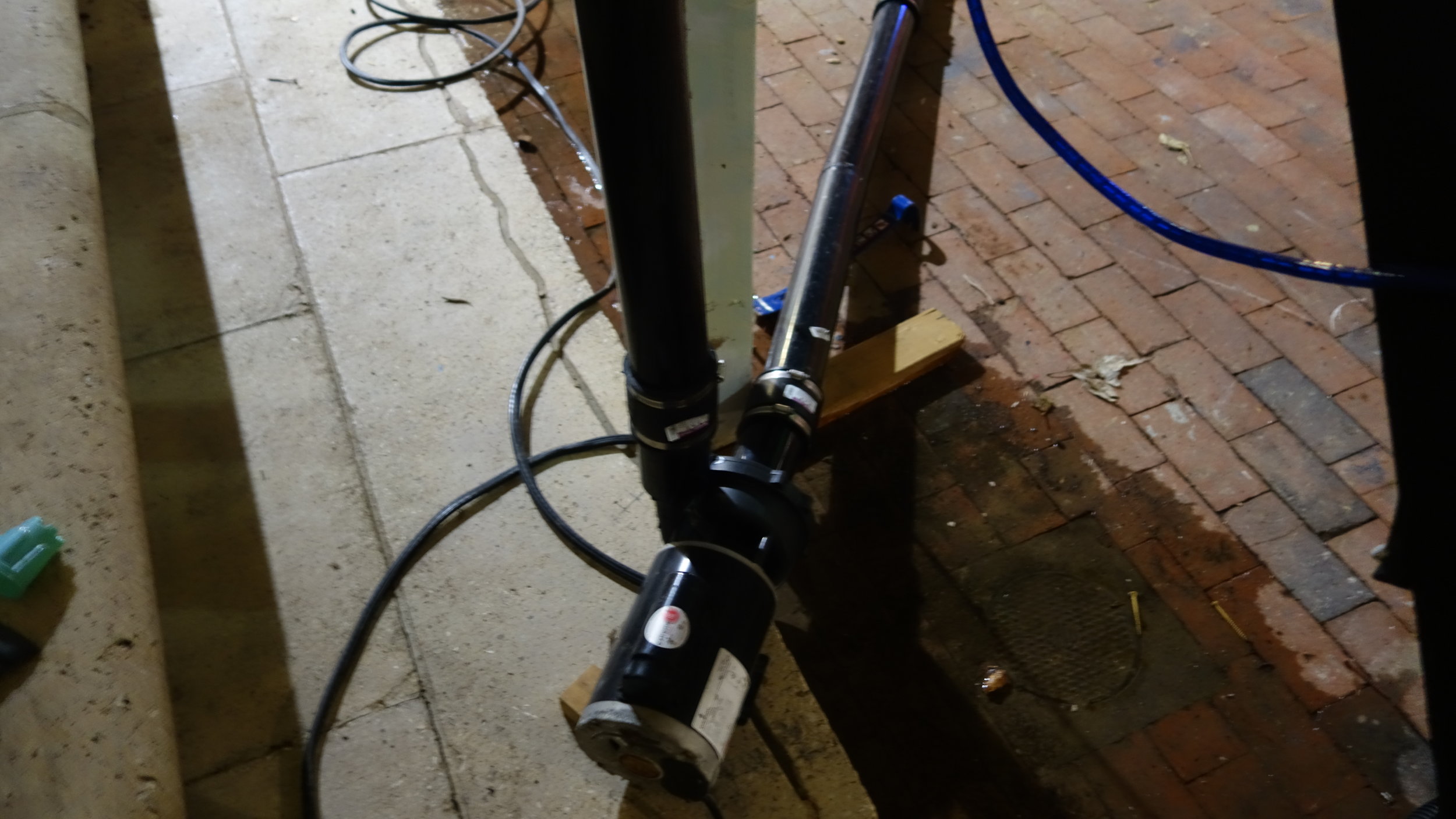
Water for our fountains was provided by two pool drainage pumps: a 1/4hp pump which has been in the house for many years, and a 1/3hp pump purchased for this project. The fountains were set up inside a flooded basin which provided the water-return for the fountains, and was a substantial interhouse project in it’s own right (our thanks to the flooding team for letting us set up in their installation).

A rough sketch of the water flow through our system. It should be noted that the line running to the second nozzle was about twice as long as the line to the first (hence the need for an equalizing clamp).
Water straight out of the pumps has a fairly jittery pressure head, we did not measure the pressure, but I would guess the jitter was around 1khz. Left unattended, this turned into lower frequency pressure variation in the nozzle and degraded fountain output. To resolve this issue, we installed an 8’ section of vertical 4” pipe, capped at both ends, as a low pass filter. Both pump inlets were positioned at the base of the filter, with the two fountain outlets, and the pressure relief valve were positioned about 8” higher up the tube. This did a good job of filtering vibrations from a single pump during testing. However, it was less effective (though still sufficient) with the two pumps both running. It seems as though it may do a better job of catching the higher frequency variations from the 1/4hp pump than from the 1/3hp pump.
Though not a perfect analogue, it may be helpful to think of this system as an RLC circuit. With the tube having many of the properties of a capacitor (the water is pressurized against a “spring” of air, giving the tube storage additional storage capacity with pressure), while the lines behave a bit like resistors (in that they reduce pressure flow) and inducters (in that there are momentum effects from the flowing water). This was not a major focus area for us this time around, but I look forward to more fully exploring this system in the future.
The overall water flow through the nozzles was tuned using a ball valve connected directly to the low pass filter. This let us bleed off pressure and helped keep the arch-lengths to something reasonable (such that the flow would remain mostly laminar). To equalize throw lengths between the two nozzles a clamp was placed on the tubing running to the closer nozzle, and then tightened until the pressure drop along both nozzle supply lines was roughly equal. This worked well, but required about 10 minutes of hand tuning to get right.
Budget:
Our original budget for this project was 275$, of which we spent about 315$ (this was not a budget we were expected to adhere to). Our largest single cost was the new pump, with much of the rest going to prototyping and brass fittings. The control electronics and power supply are not included because I either had them already (power supply) or purchased them separately (arduino). Not including prototyping costs, we ended up spending about 25$ per nozzle in final parts.
The most significant areas for cost reduction are likely the brass fittings (4$ at home depot, 1.5$ online) and the vinyl tubing which is cheaper in bulk, or which could be replaced with hose at lower cost.
IMPROVEMENTS for next time:
Use a collar or other quick-connect mechanism for holding the two ends on. This would make it much easier to prototype. Something based around 1/4-20 cap screws would be good because you could then use an impact driver to set it up and take down.
Real fiber optic is not that much more expensive than the acrylic for small numbers of fountains, and seems likely to work much better. For fountains where light is a priority I would absolutely make the switch. On the other hand, for fountains where bulk is important or where other effects are the focus then the current design works well.
Resources:
Similar Project Link: https://www.youtube.com/watch?v=o5L6W0YoAd4&t=603s
Similar Project Link: https://www.youtube.com/watch?v=HBeQkX0WzCo
Similar Project Link: https://www.youtube.com/watch?v=SjOZmby5K8c
Similar Project Link: http://laminarfountain.blogspot.com/2014/03/water-works.html
Light Pipe Reference: http://www-eng.lbl.gov/~shuman/XENON/REFERENCES&OTHER_MISC/Lightpipe%20design.pdf
Project Documents: [click me]
Testing Pictures:

Testing maximum flow rates with one of our earlier nozzles.

Unintentionally siphoning off the water test bucket through the nozzle. After this we started placing the nozzle above the level of the water, but it was fun to see this in action.

Some early testing with our 6” nozzles. You can see that the nozzle was hooked directly up to the pump with no filtering.
The pipe-clamps let us change the internals relatively quickly, without a great deal of fuss. Overall I liked the design, though I’d probably build some threaded rods into any new future nozzles to serve the same purpose.

Appendix A:
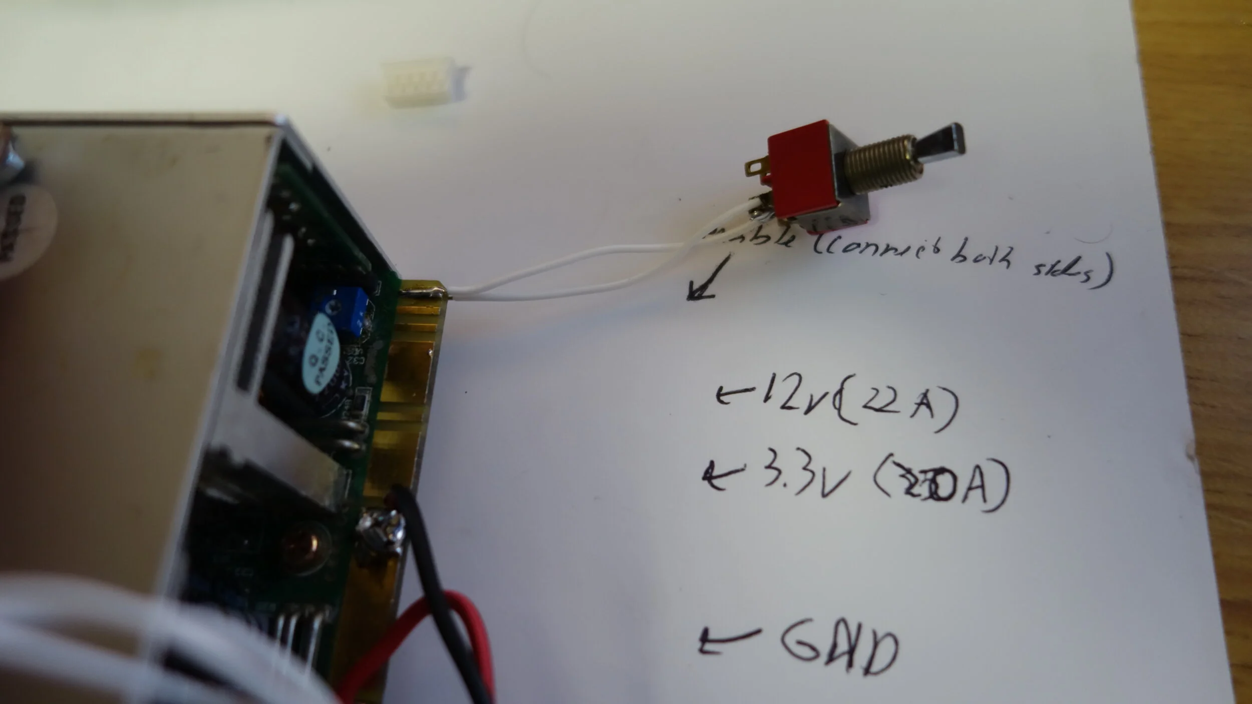
I have been getting some questions about where exactly to hook up the enable jumper for the supply, so I’ve added this picture to clarify. The connection should be from the top right pin to the bottom left pin as shown above. You can use a plain jumper or switch depending on your preference, but do note that they pads can be a touch delicate so you want more strain relief (and insulation) then is shown in the test setup above. As always, don’t hesitate to reach out (use the contact form under “about”) if you have any questions.