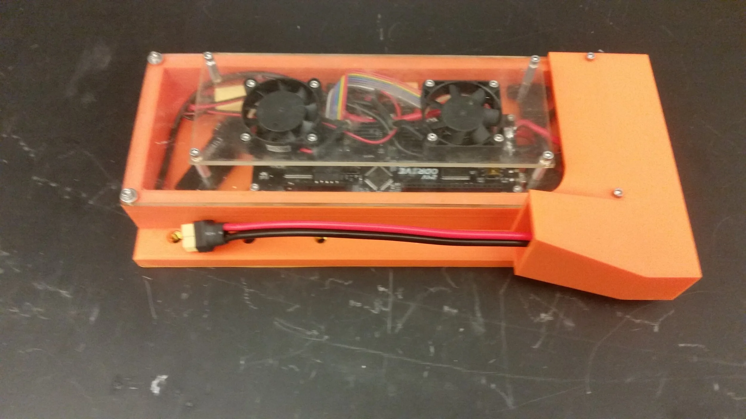
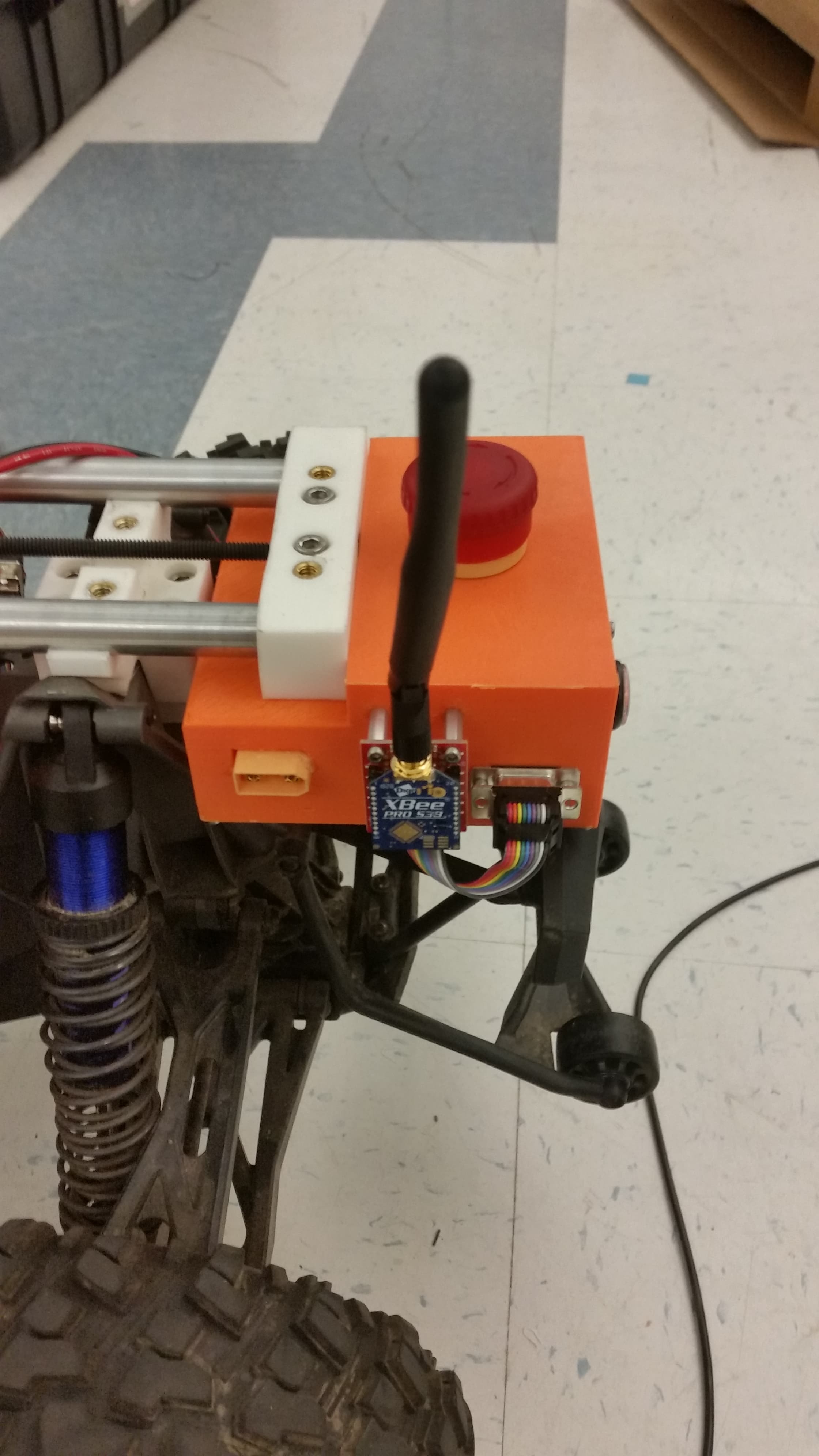
The autonomy package, removed from Balto immediately prior to shipping.
Summary:
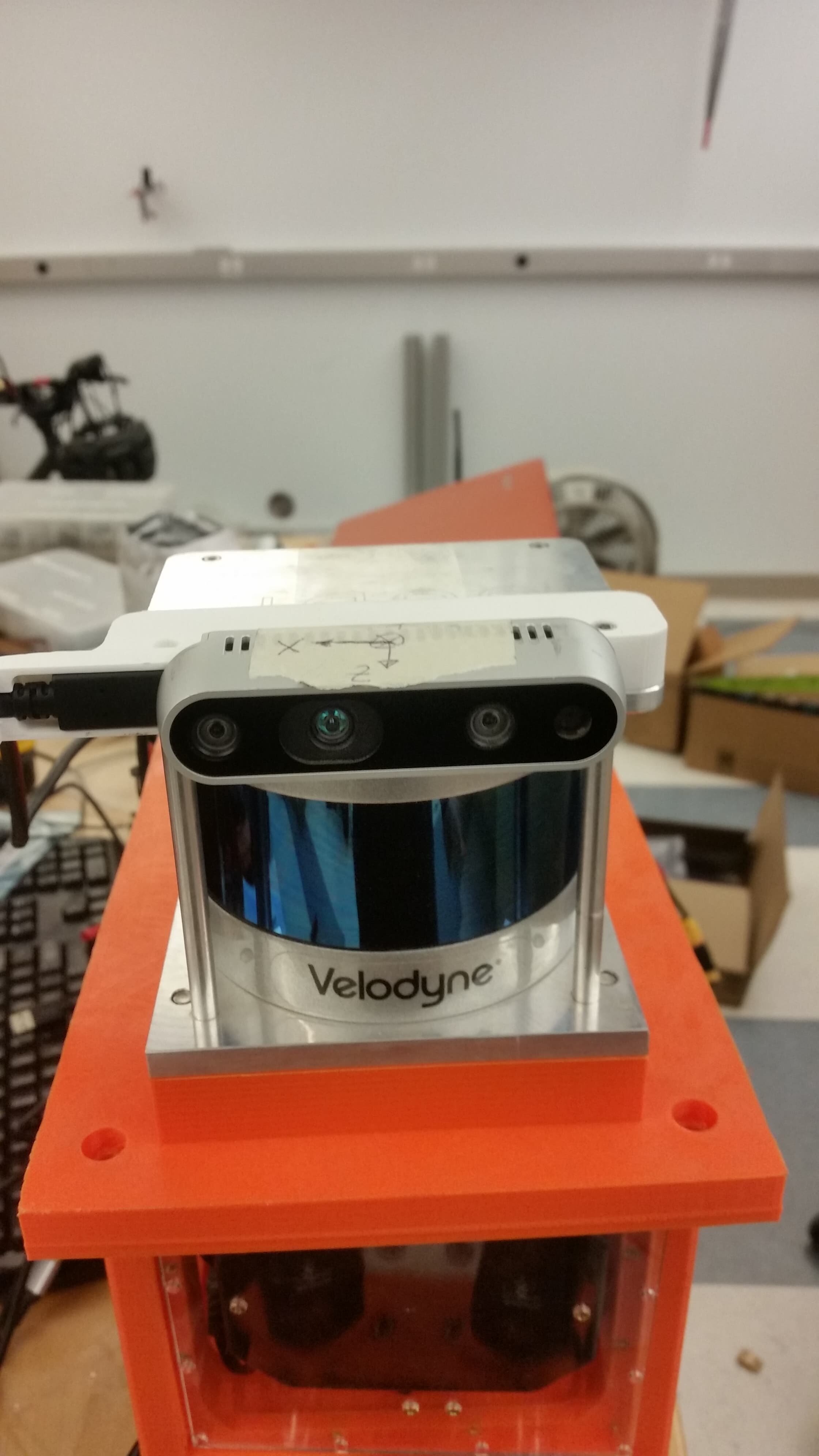
The compute housing holds the NUC, Velodyne box, TX2, router and Ethernet switch. This is the first integrated version of the housing where all of the components are in one enclosure. It is designed to be dust and splash resistant with interchangeable laser cut panels for easy access to the internals. This is the housing that we used on Balto when it ran in the tunnels circuit.
The housing itself is composed of three printed parts, and three laser cut panels. The printed parts should be printed with thick walls, and take a combined 40 hours on a crafbot plus at medium printing speeds. The three laser cut panels are designed to 3D printable if need be, though using a laser does allow for nice graphics.
This version of the electronics housing was completed in just over a week and, although I like it on the whole, there are still a lot of modifications I want to make. In particular to do with weight distribution and water resistance. With that in mind, I have chosen to include a slideshow of assembly photos rather than a full build log. If you are building up this version (and to be clear I do like it rather a lot) definitely feel free to reach out and I can provide you with more detailed instructions.
Favorite Elements:
This design had a few elements that I felt worked particularly well.
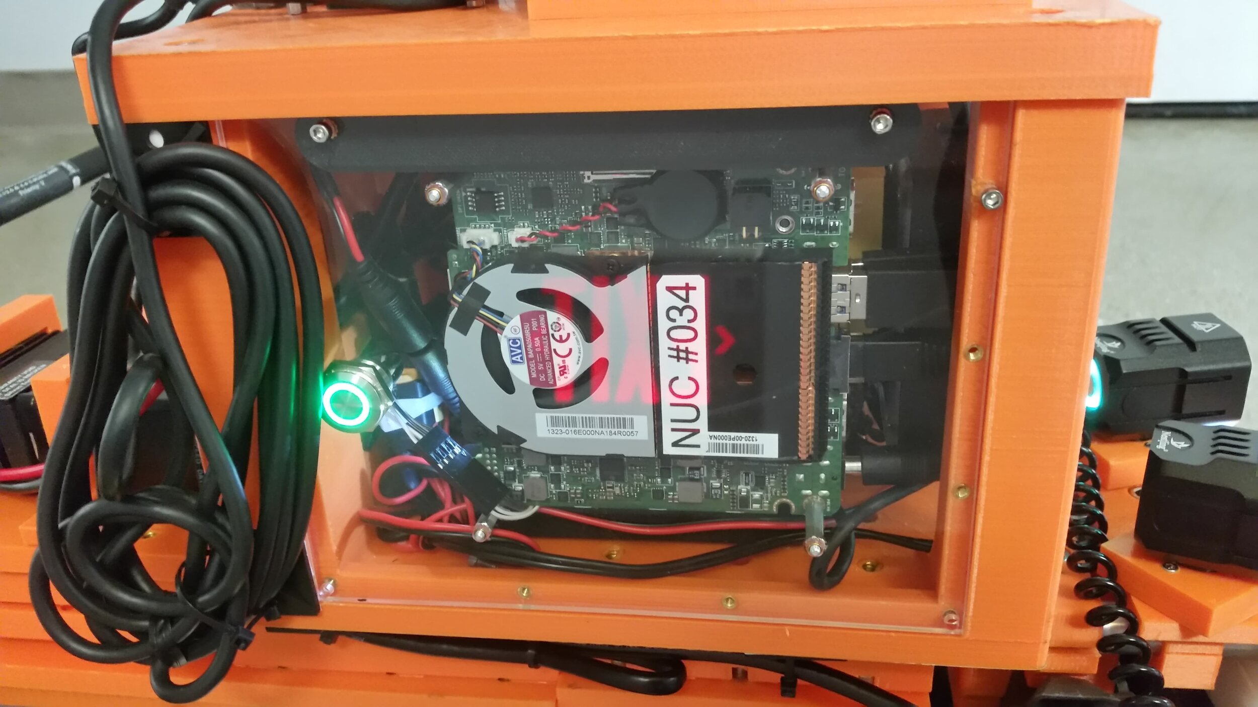
NUC Switch - From a purely aesthetic standpoint, the NUC’s power switch is definitely my favorite part of the housing. It’s got a green led ring very reminiscent of a lightsaber, and mounts nearly flush to the outer panel. On a practical note it is both easier and more water resistant than just having a hole to use the built in one.
Acrylic panels - Using acrylic wall panels let us iterate the mounting design much faster than if we had been using printed panels. They are also clear which is nice for checking that all’s well. The panels are still designed so they can be printed if the laser ever goes down.
Velcro - Our original design had everything mounted with screws. Using velcro for some of the lighter weight parts made it much easier to assemble and disassemble things during the debug phase.
Waterproof wire outlet - Using a compressed foam sandwich to pass cabling into and out of the box worked perfectly. It’s easy to install and remove, but also virtually splash proof.
Aluminum reinforcement - Using aluminum reinforcement rods to help prevent de-lamination seems to have worked. Although we haven’t yet had any highly energetic crashes.
Areas for improvement:
This version of the housing worked well, but it was designed in a short period of time and there is certainly room for improvement. A few particularly notable shortfalls can be found below:
Weight - The NUC, Velodyne, and Velodyne converter are all above the flying bridge. This results in a dangerously high center of mass. Addressing this will likely require a full redesign, but remains a top priority.
Dust - The lack of filters means dust can build up in the system over time. Was not an issue for short-term operations, but could become an issue over multiple days or weeks of testing.
Access - The system currently requires removing about 8 screws to address any wiring problems. Not bad, but certainly less convenient than say snaps or clamps. The top is 1/4-20 while the sides are 4-40 which I also do not love.
Screws - We currently use both 3/8 and 1/4 length 4-40 socket head cap screws. Switching to just the 3/8 would require minimal modifications and would improve the assembly process.
Heat - Under certain operating conditions it might be possible for the TX2 or NUC to overheat when running full out. We did not experience this at competition, but better thermal management remains a priority.
Power - A more considered plan for power distribution and regulation would improve reliability and reduce the risk of accidental damage during assembly.
Build Photos:

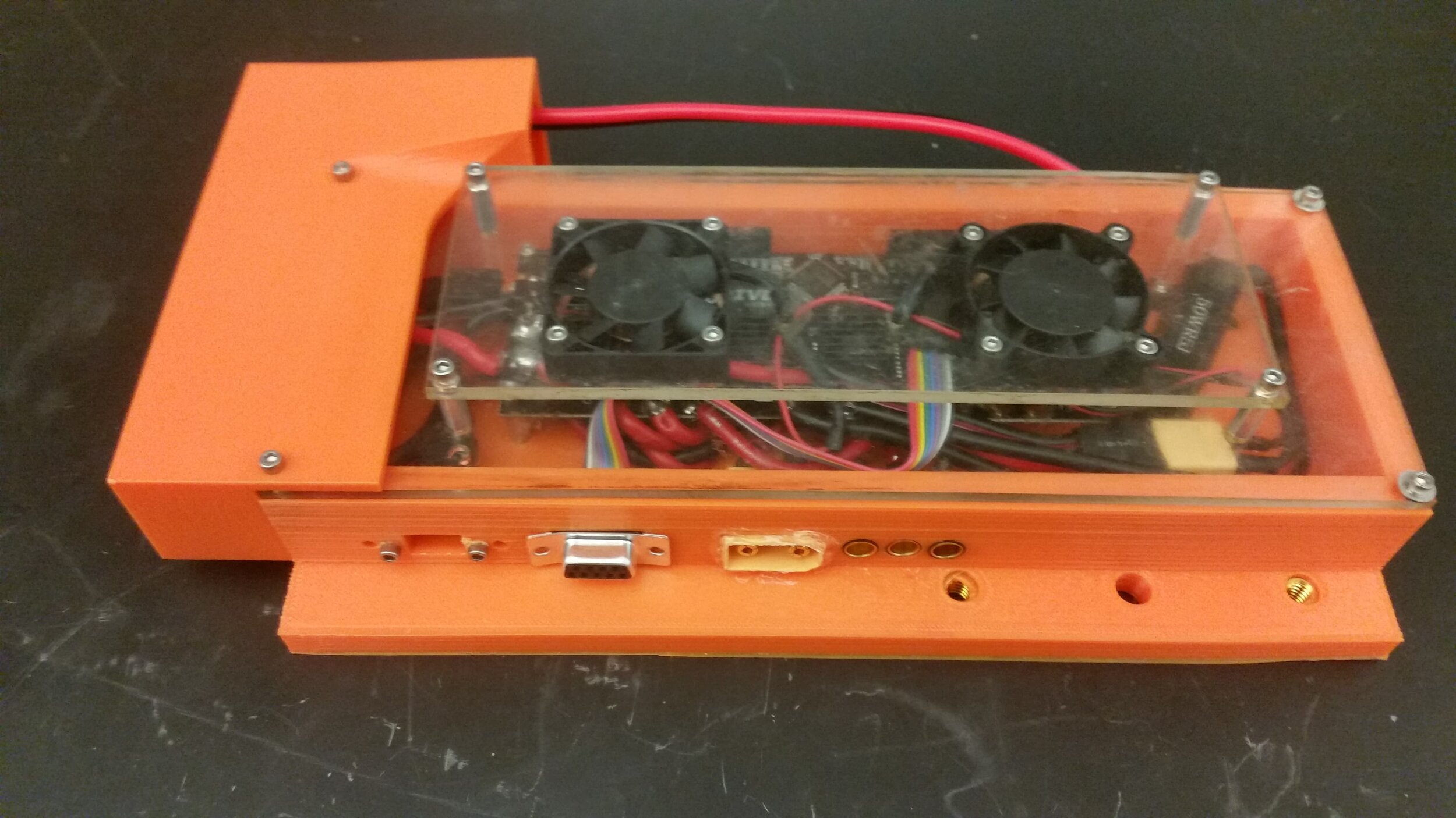
The housing base and lid. The two pieces interface securely with a 45 degree chamfer and are held together by the 4 1/4-20 screws. This setup worked well and was very robust in practice, I would use it again.

The upper us hub was held into a 3D printed mount using Velcro.
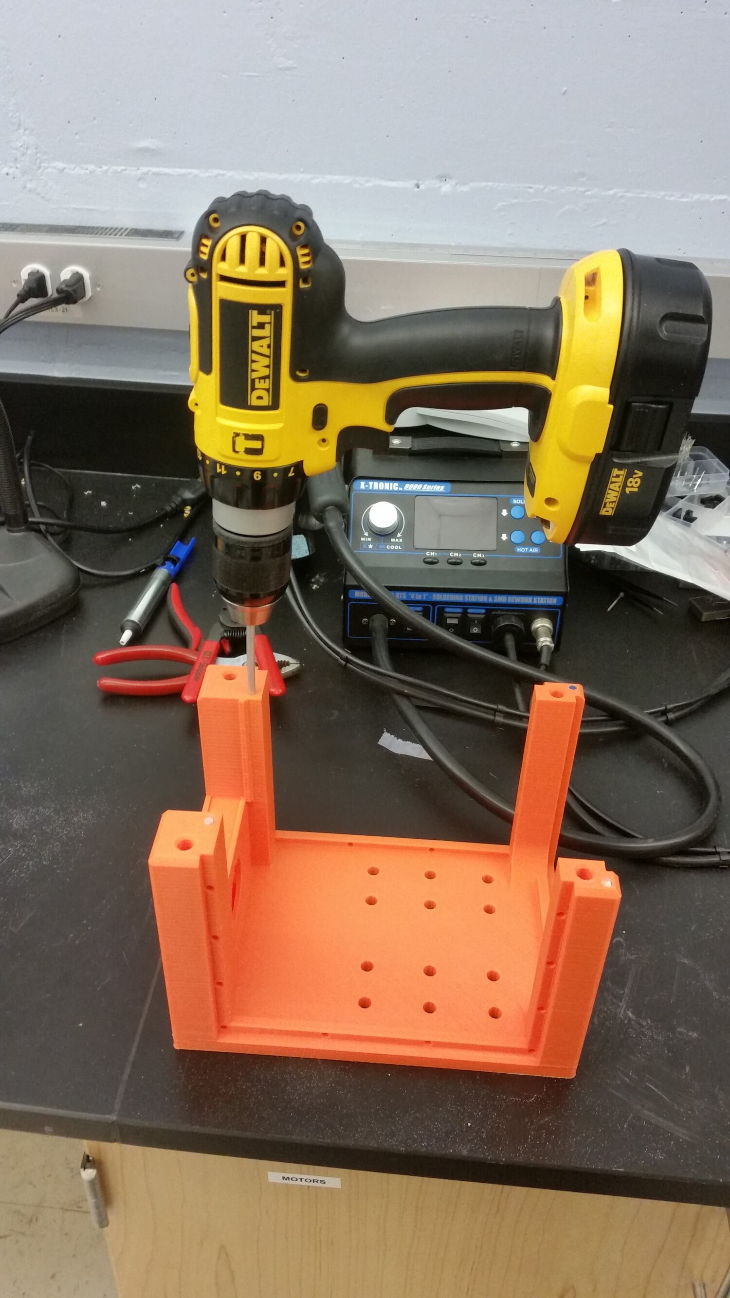
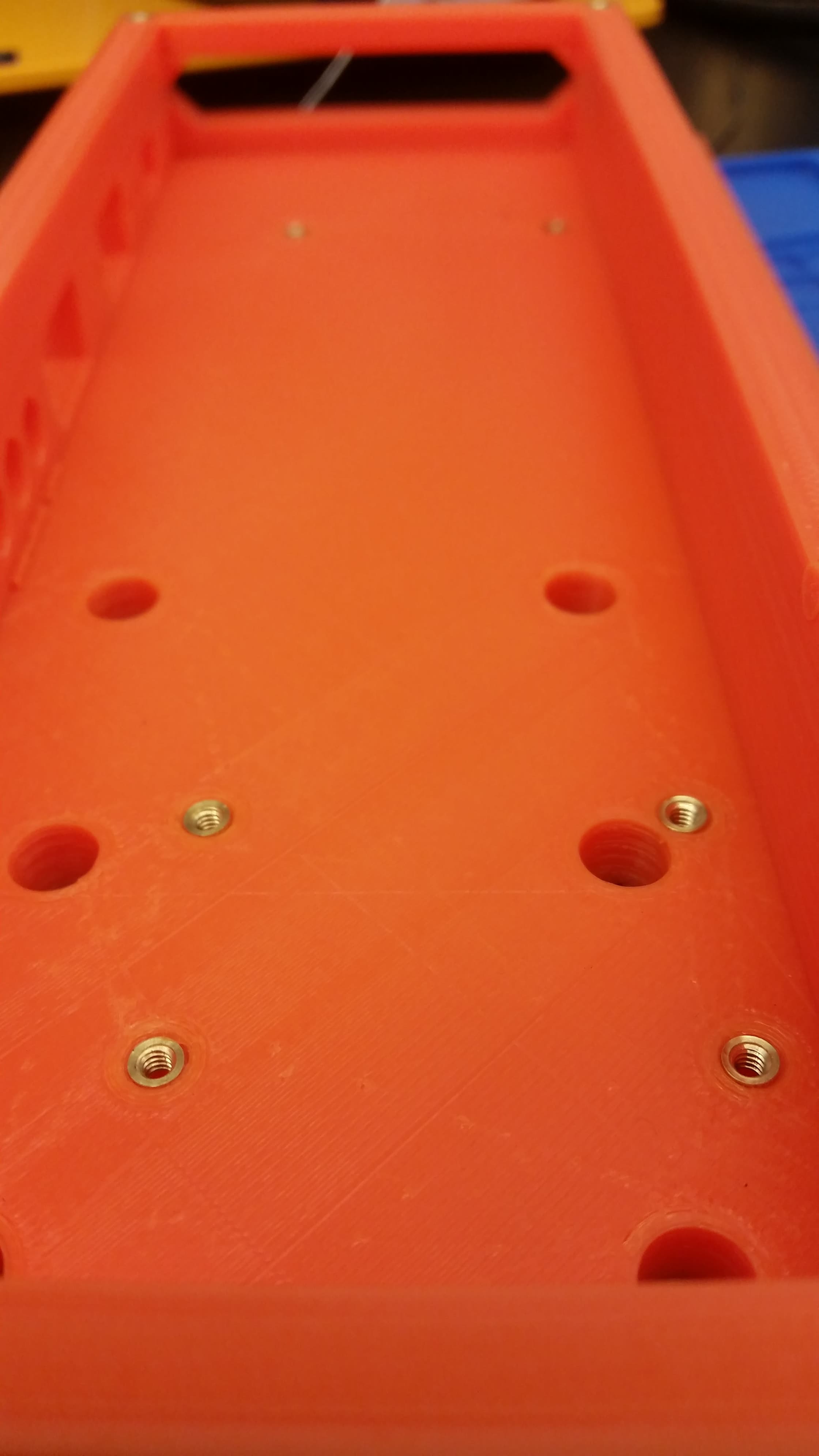
The aluminum rods were cut to length and then installed with a drill to help ream out the hole. CA glue, or epoxy should be added to fight laminant failures. If spinning the rods proves insufficient then grinding a separate rod with a d-bit tip will help.

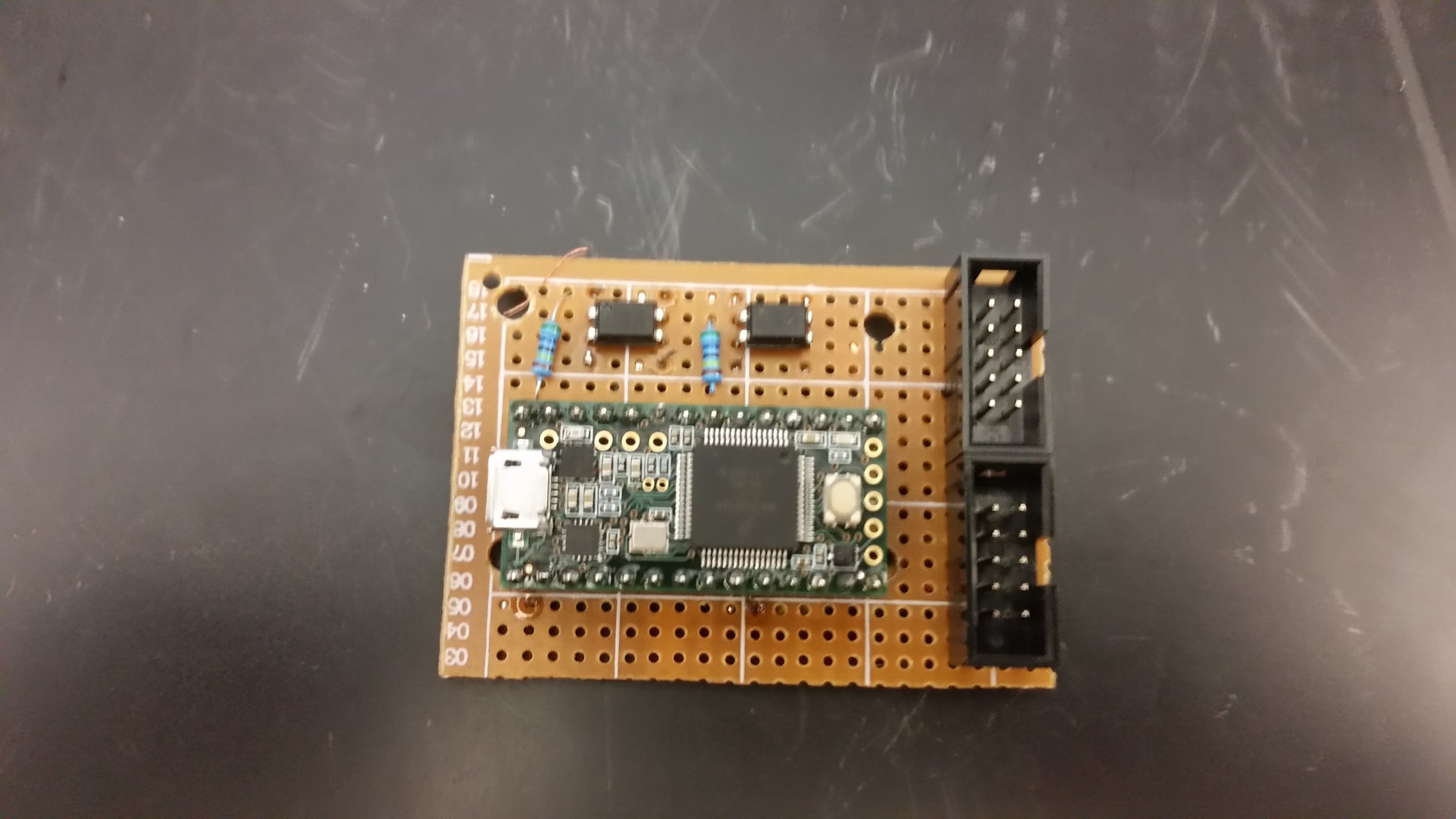
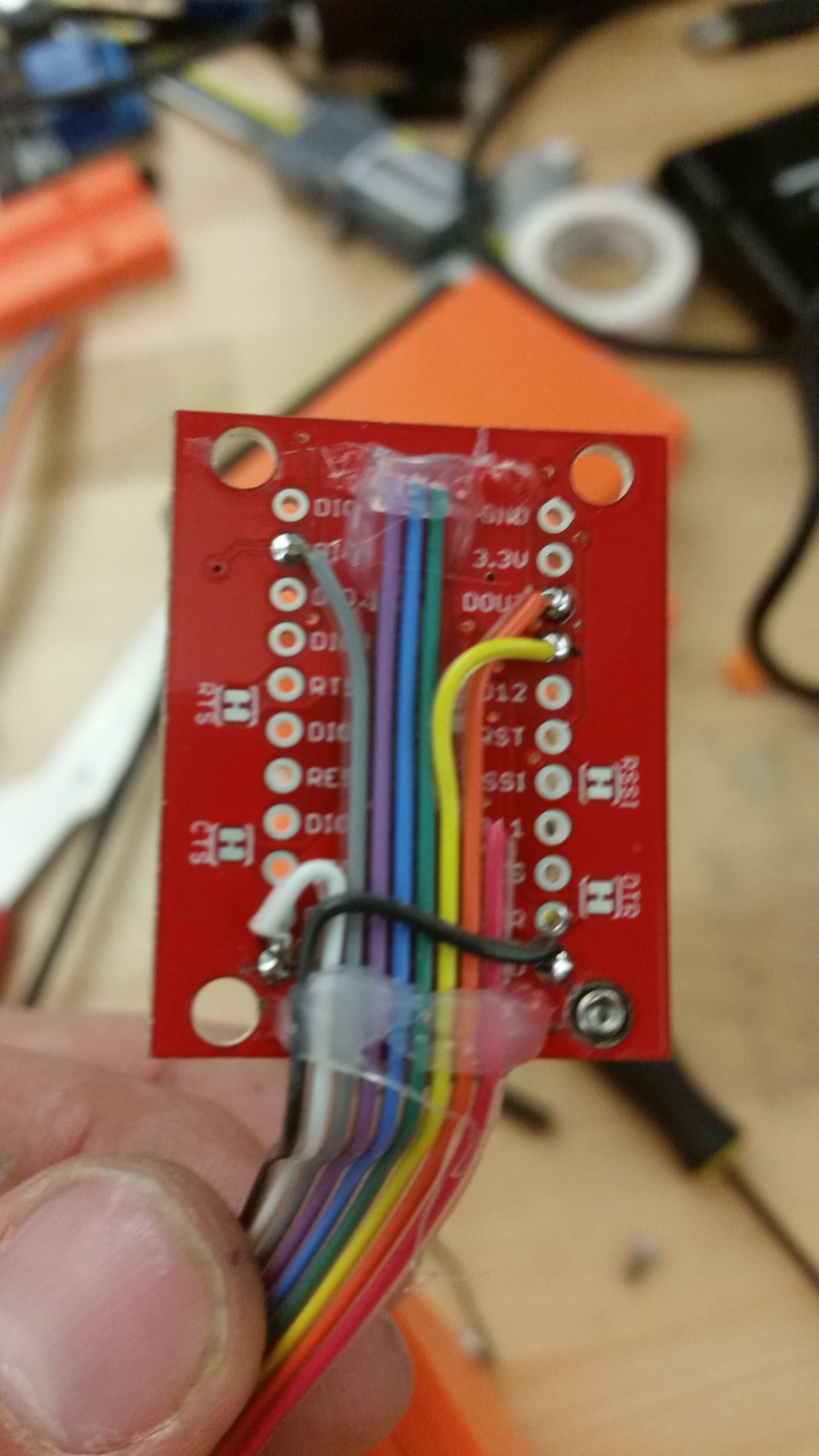
We were unable to get the correct size of header shipped in time, so we soldered our switch extender directly onto the NUC. (You can see the hole we used to use for poking the onboard button.
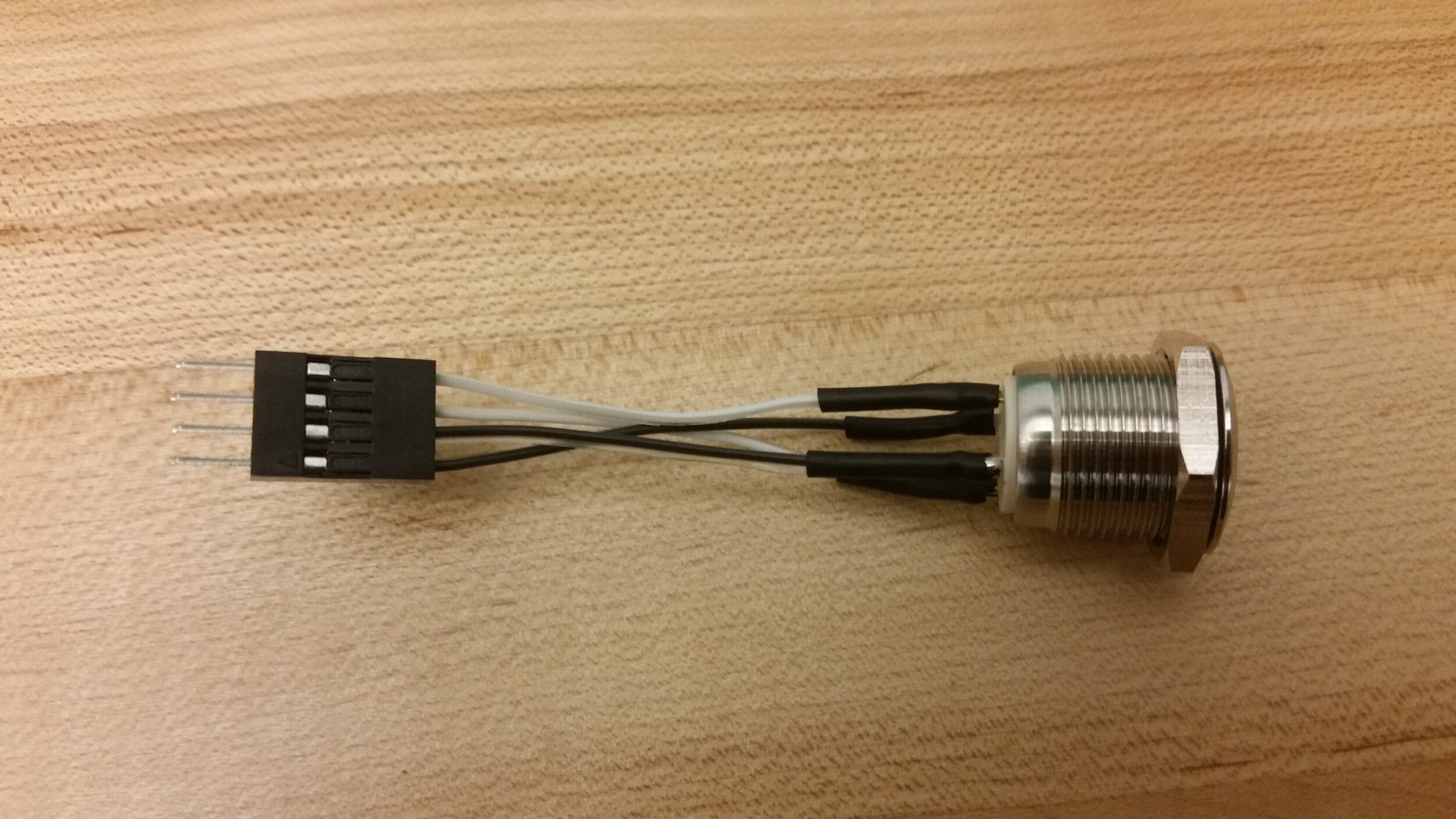
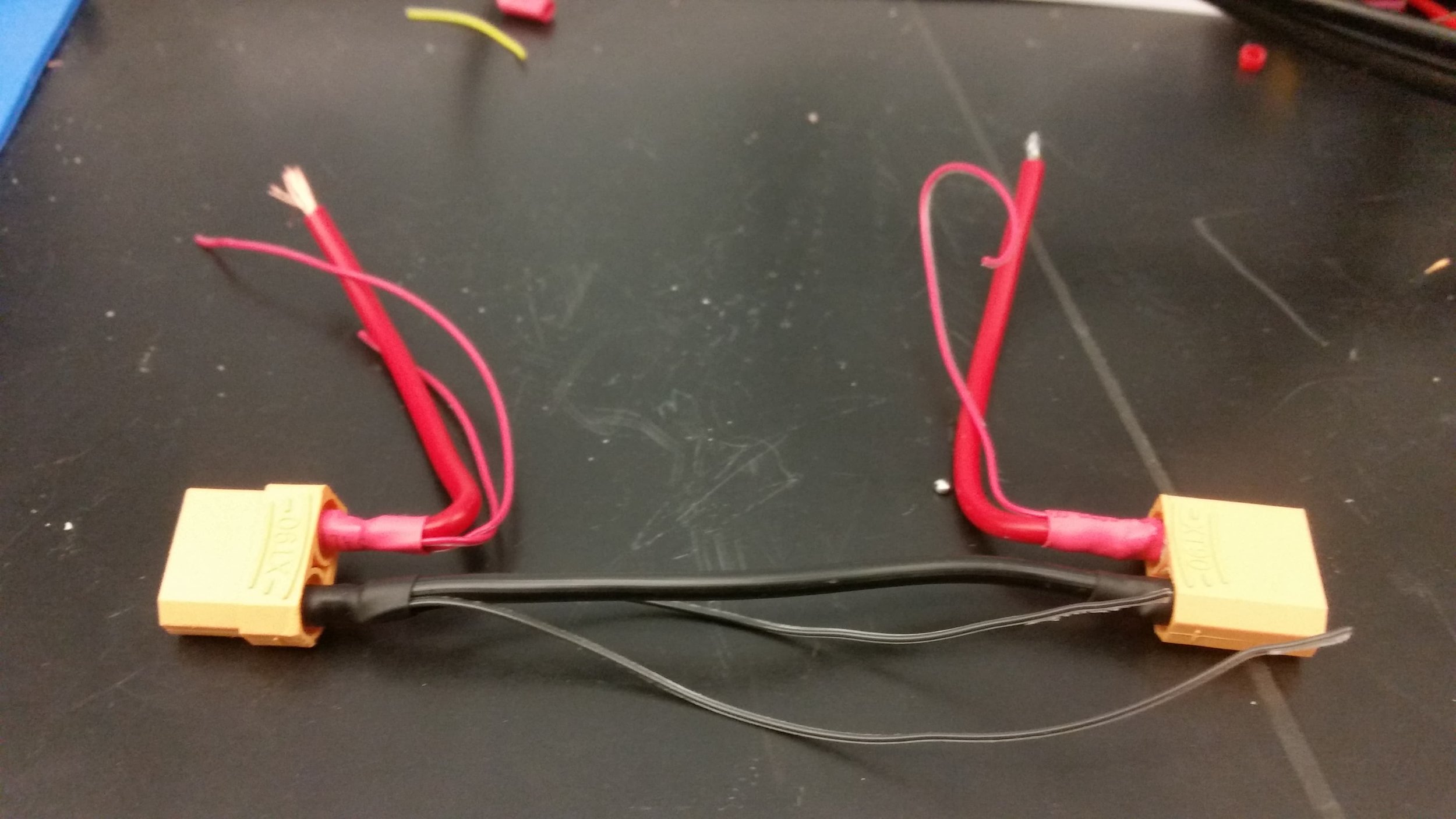
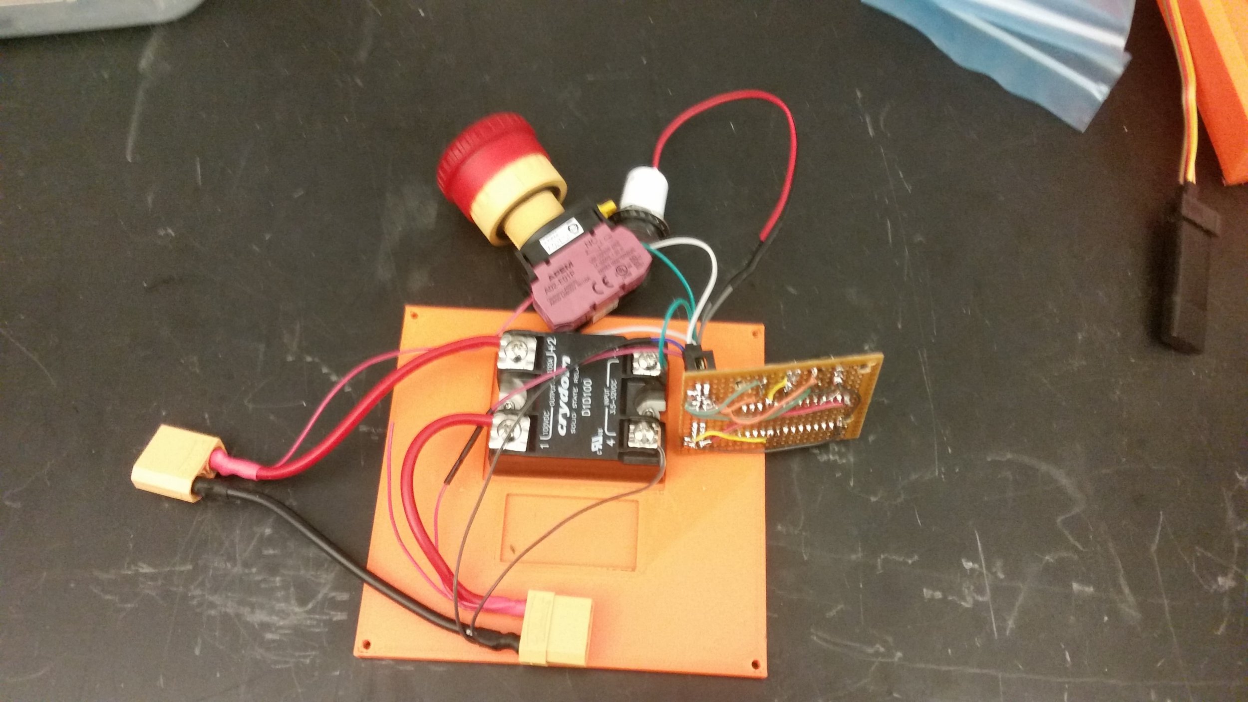
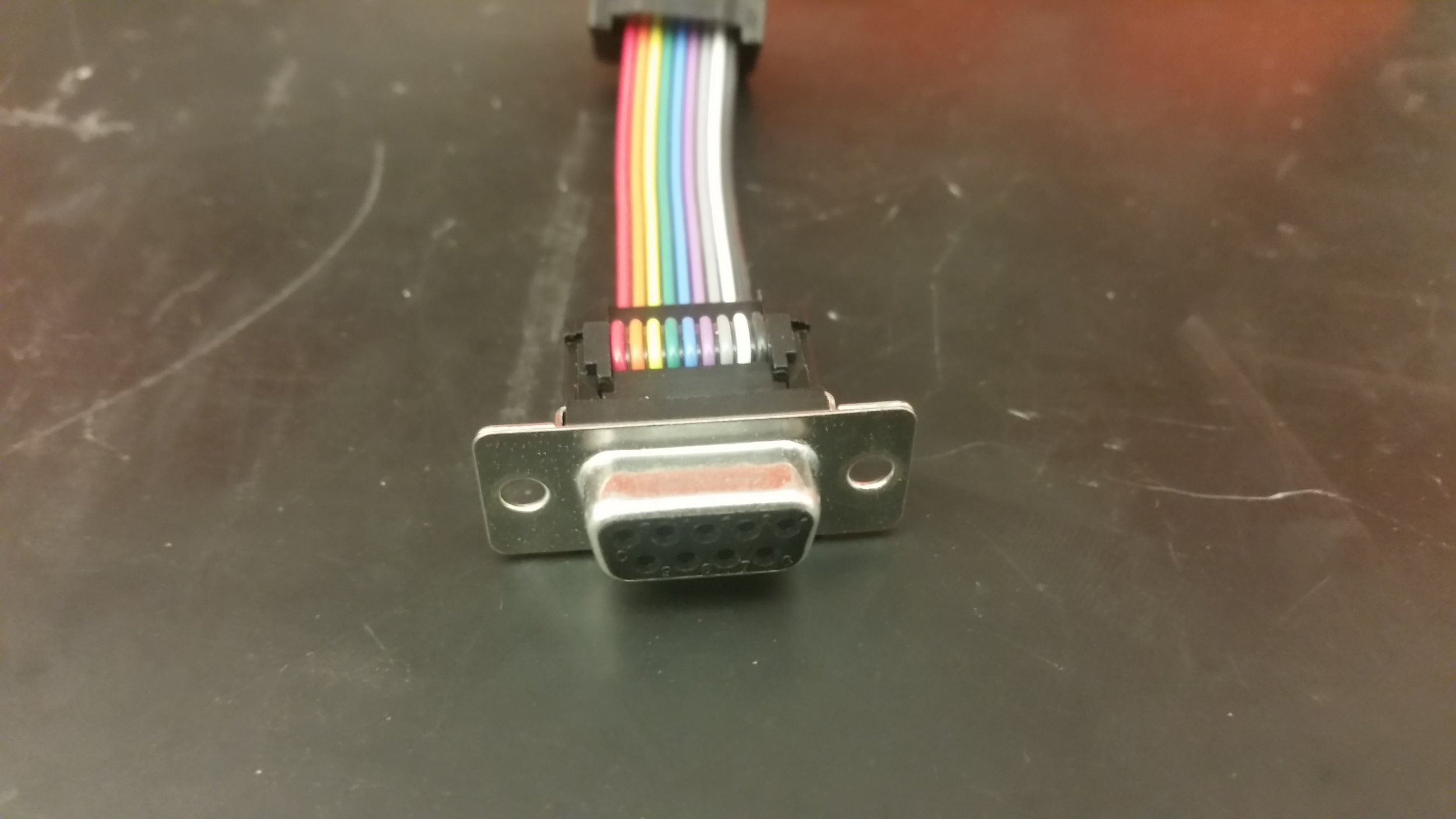
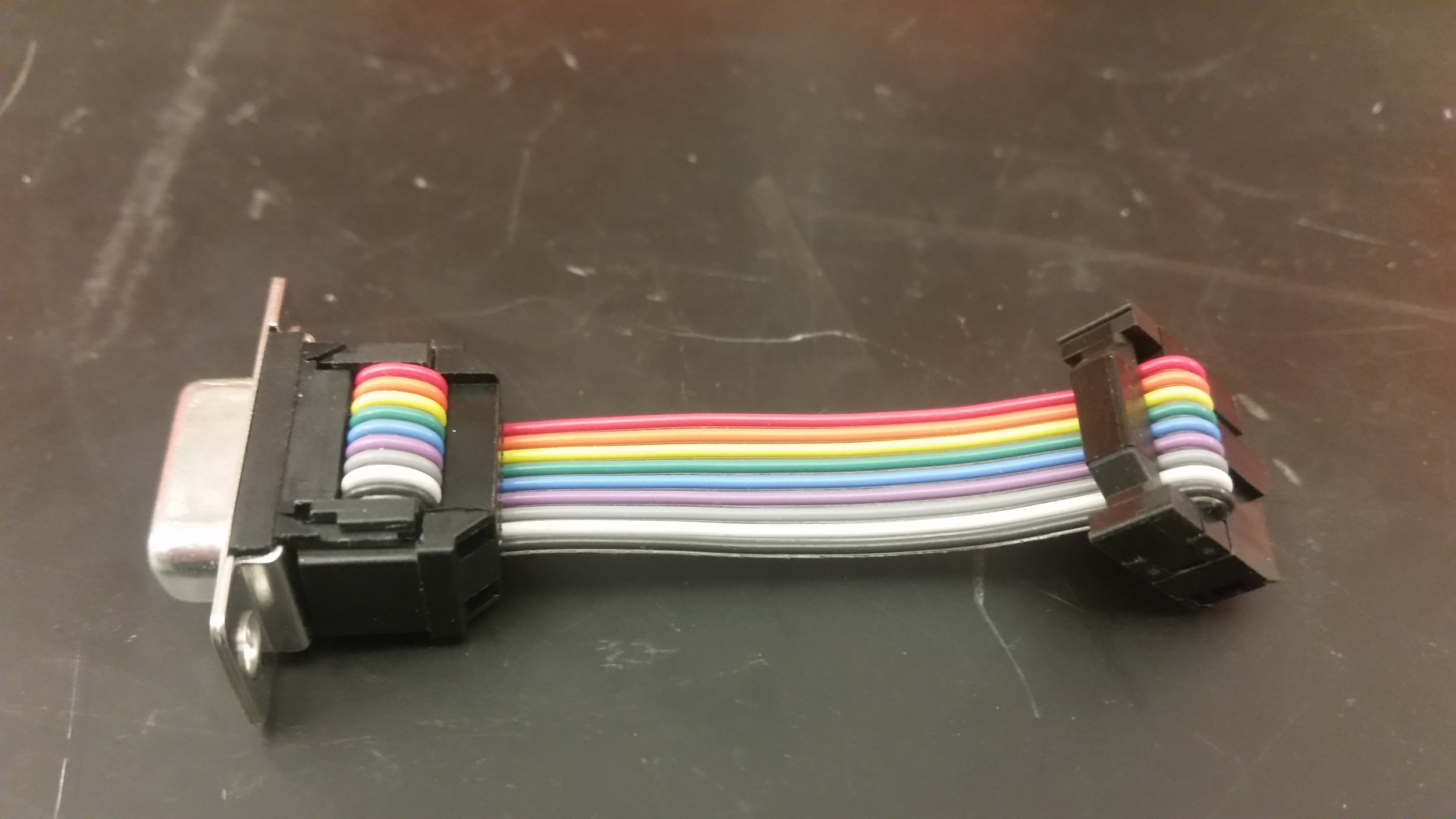
The button side of the connector. It is connected white to white and black to black so that the button and LED go to the correct parts of the header.

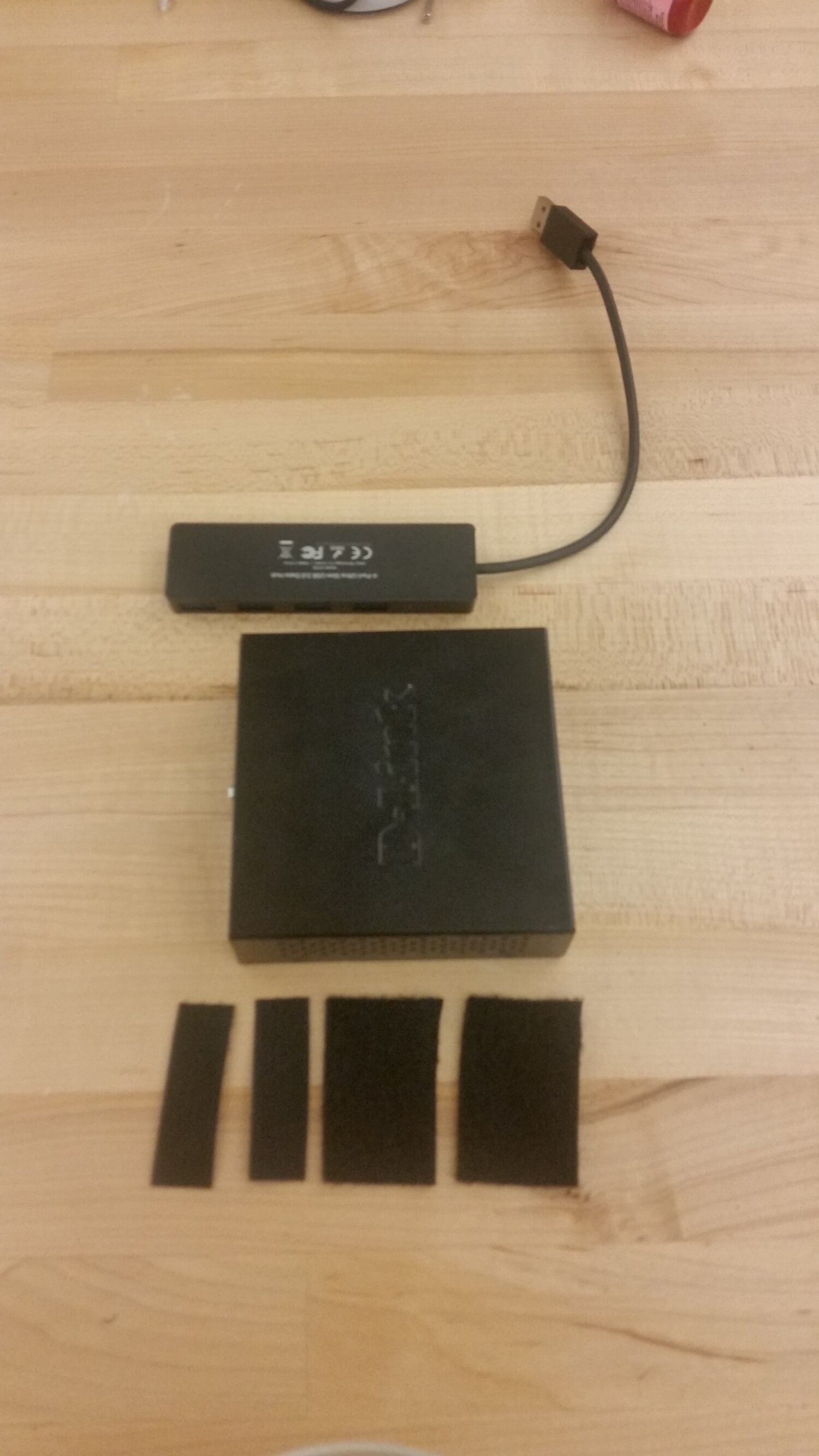
Velcro was used for holding down the D-Link, TX2, and lower USB switch.

The lower USB switch and D-Link were Vecro’d together, and then Velcro’d to the floor of the housing.

The TX2 was first mounted on a 3D printed plate with standoffs.

All of the various components fit with a bit of room to spare (though not much).