Purpose:

The goal with this build was to prototype a flat bottomed RC boat with as little investment of resources and engineering time as possible. To that end, this boat features a 3D printed hull (low time commitment to fabricate), with propulsion hardware scavenged from a team member’s quad-copter, and a controller borrowed from the shop. Although less polished than most of my projects, the payoff in terms of [lessons learned] / [time invested] was fantastic.
ME72: This is the first in a series of posts about ME72, a design capstone course in which 5 person teams compete to build 3 robots then can to fit that year’s competition. This year, the course is amphibious in nature, with a strong emphasis on ball manipulation.
Design:
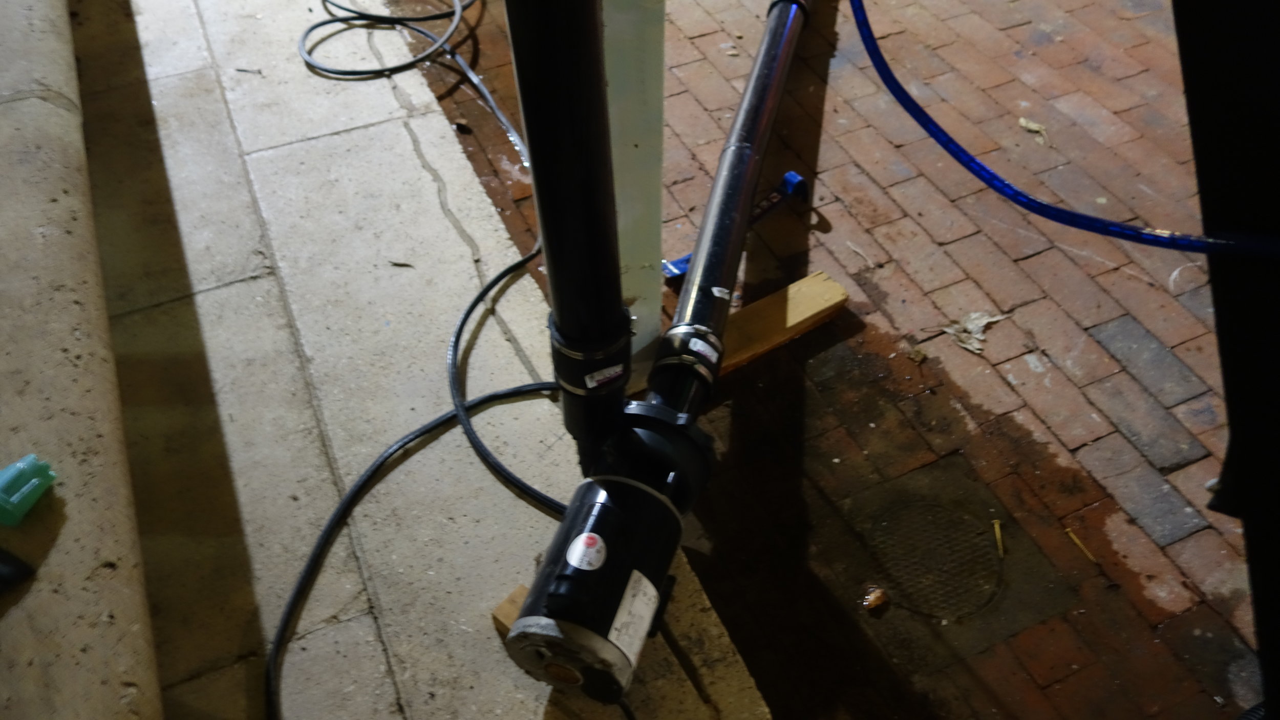
I choose an air-boat for our first prototype, largely on the grounds that it is by far the simplest and cheapest motion system to build. The thrust-tower is designed to support at most an 8 in prop, with provisions made in the model for increasing the height as needed. This provided adequate power for hull-testing, and is most likely what I would use for future hull-tests as needed.
Using a half-height (4in) steering fin reduced print time, and made the model easier to assemble. However, it did result in a noticeable decrease in overall control authority relative to a full-height fin. This was most noticeable at high speeds, but was an issue throughout the power curve. In the future, this could be addressed with a taller fin, or by increasing the maximum turning angle of the fin beyond it’s current 10 degrees.
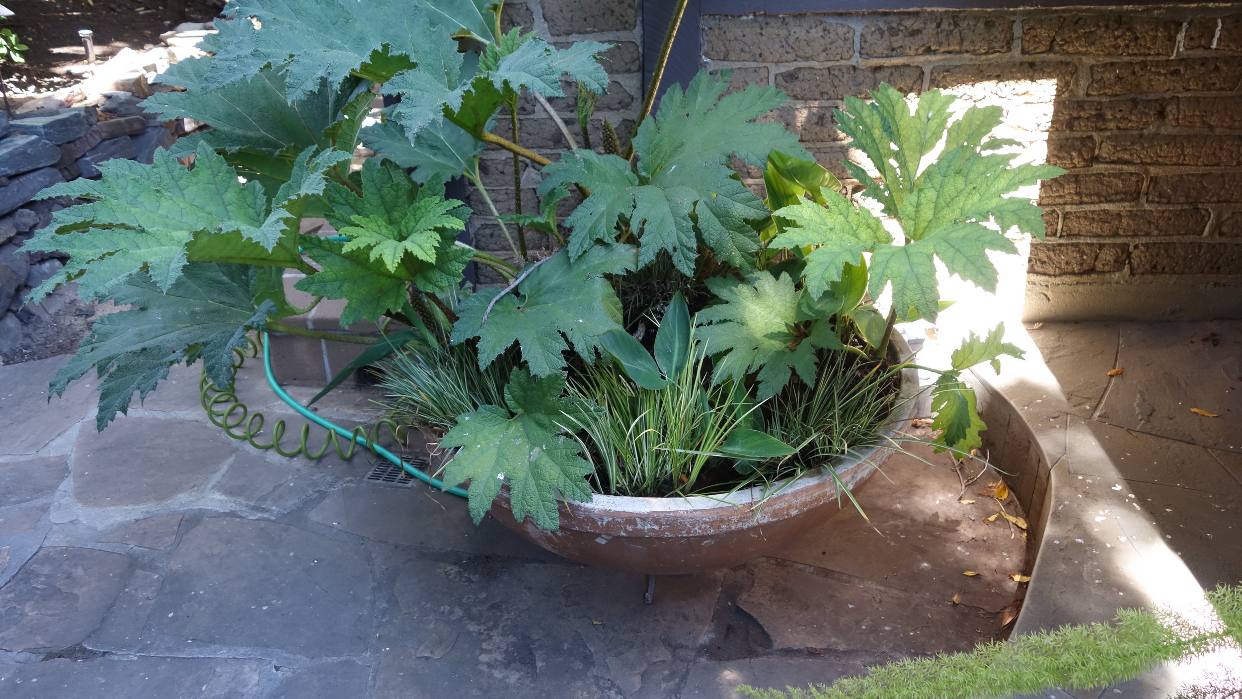
Although the hull doesn’t have any water-tight compartments, it does feature a sealed deck. This allows it to swamp, but not sink, when taking water over the sides. Although this proved unnecessary in normal operation (no water was taken over the stern), it did prove useful when a friend accidentally drove the vehicle through a fountain.
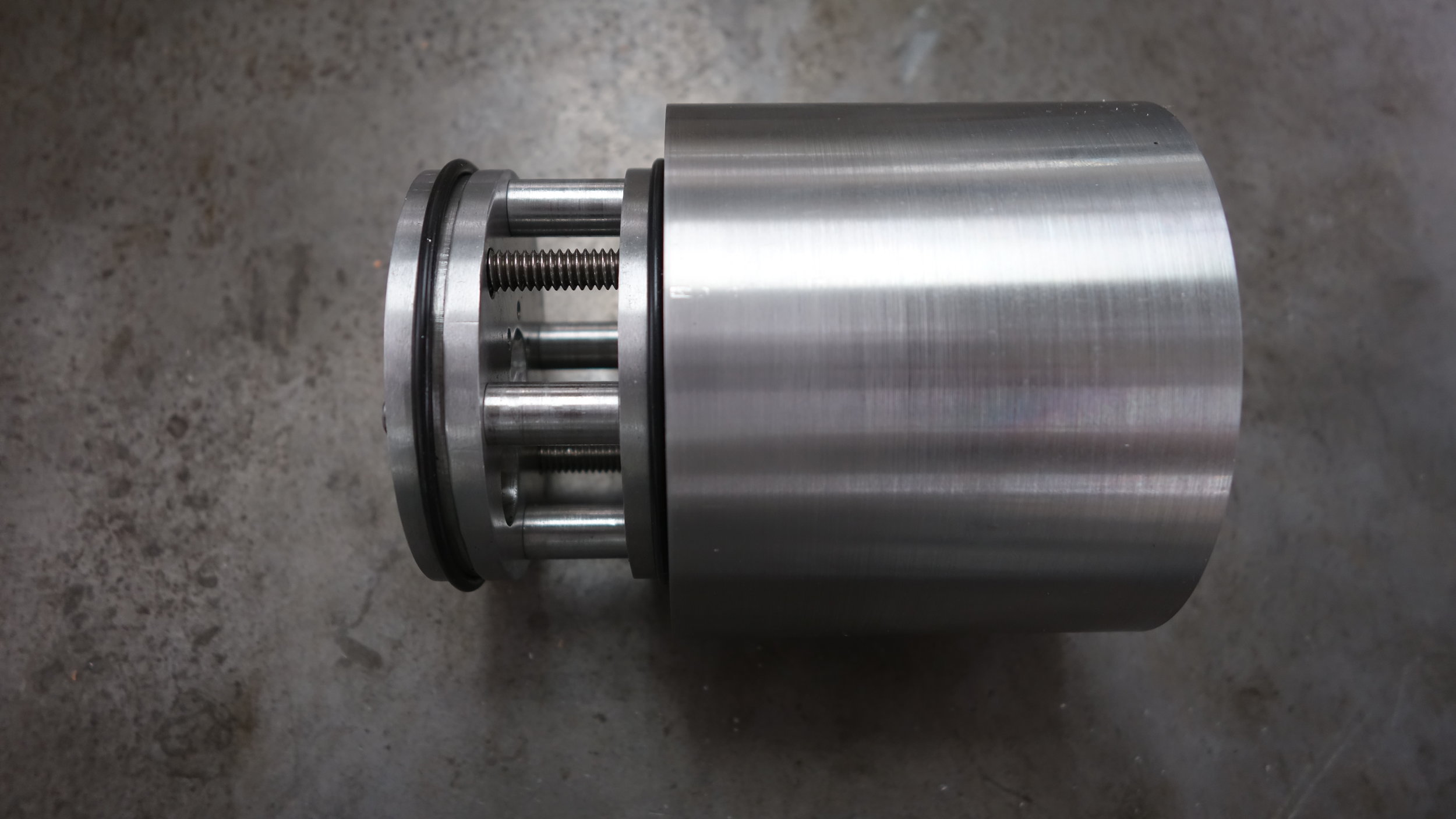
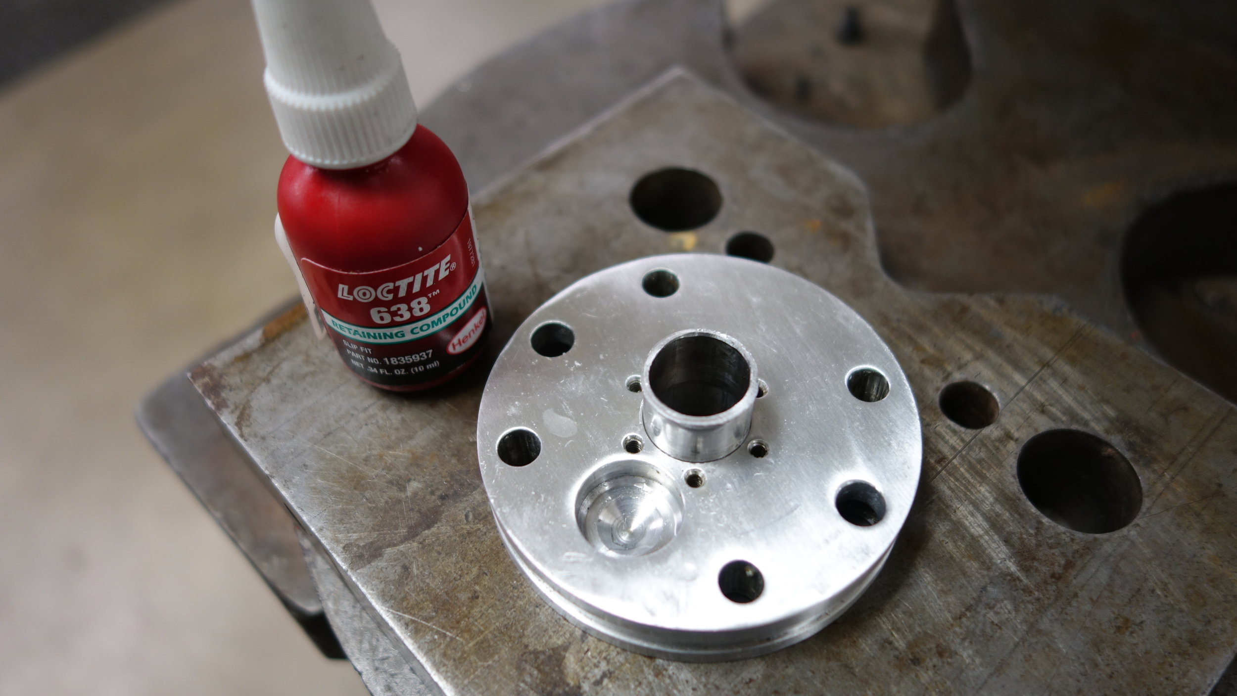
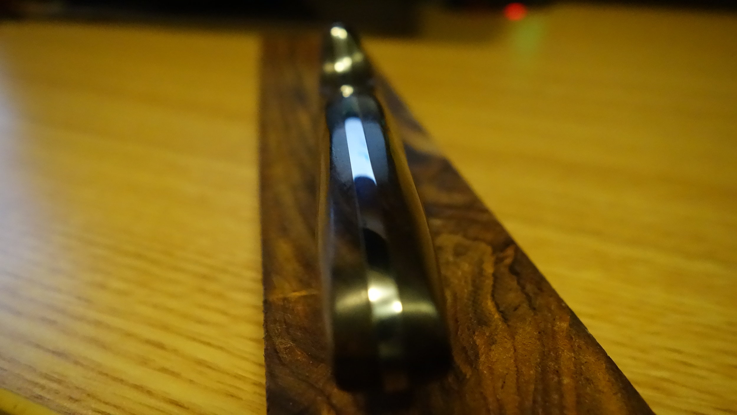
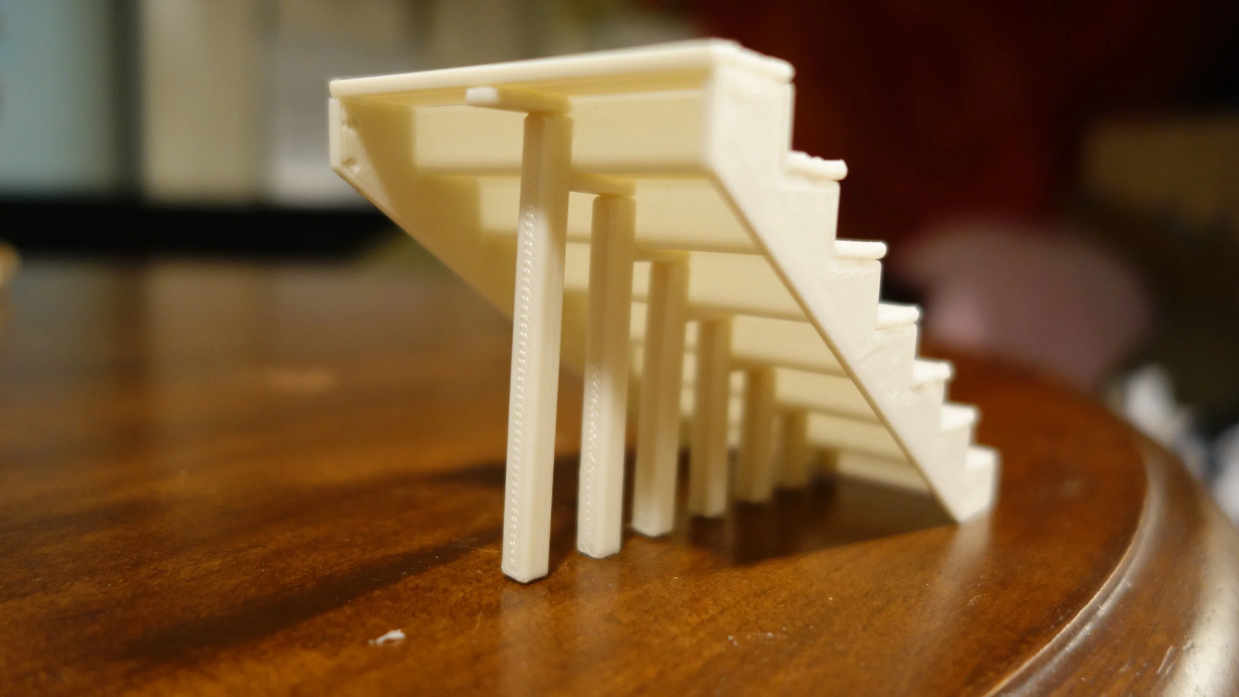
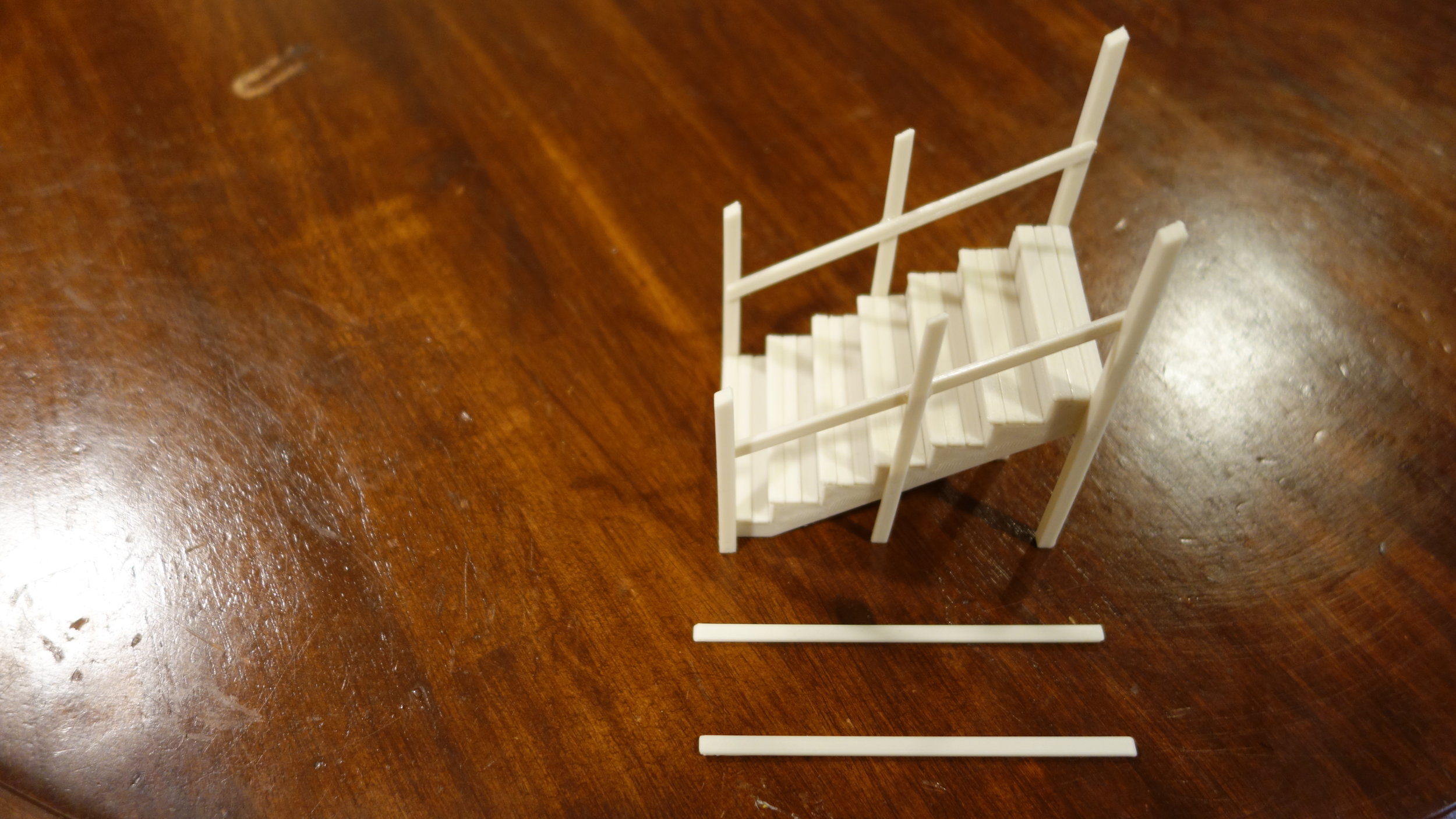
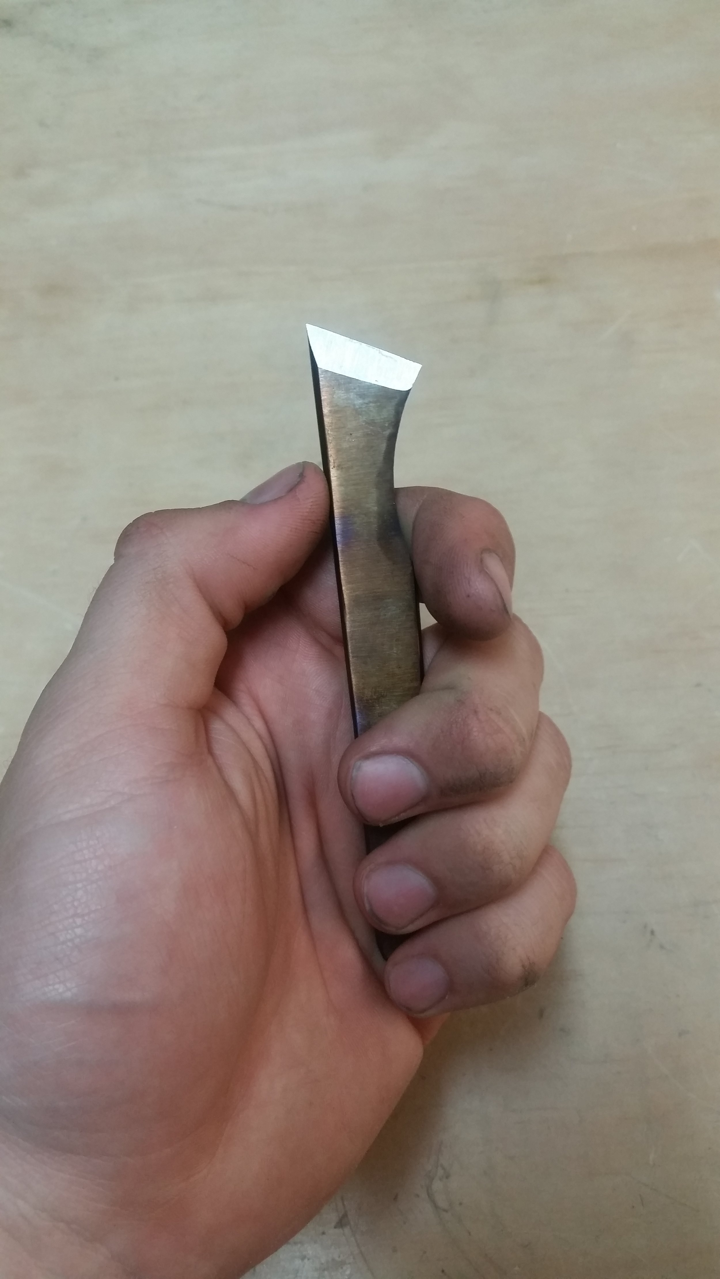
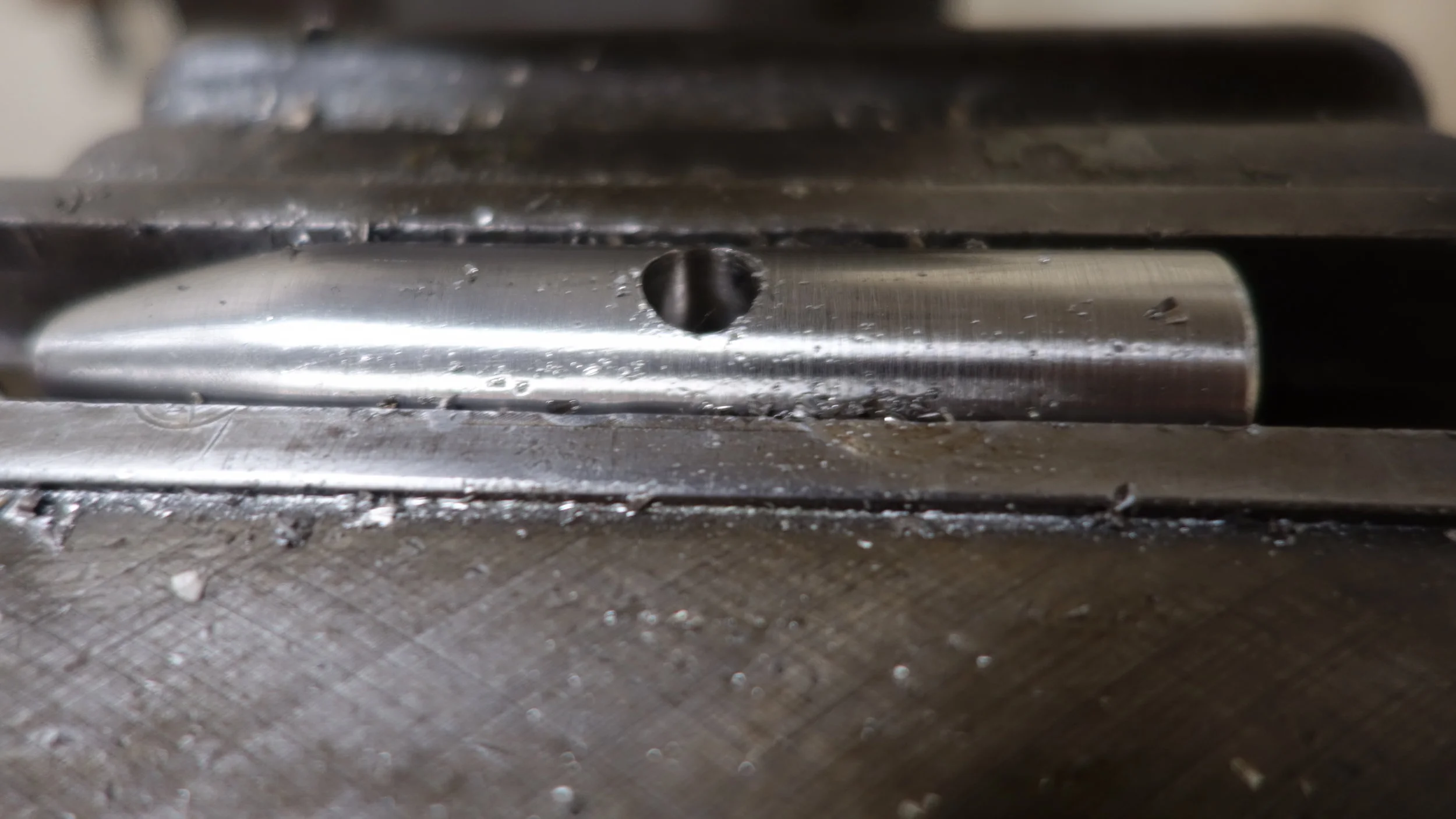
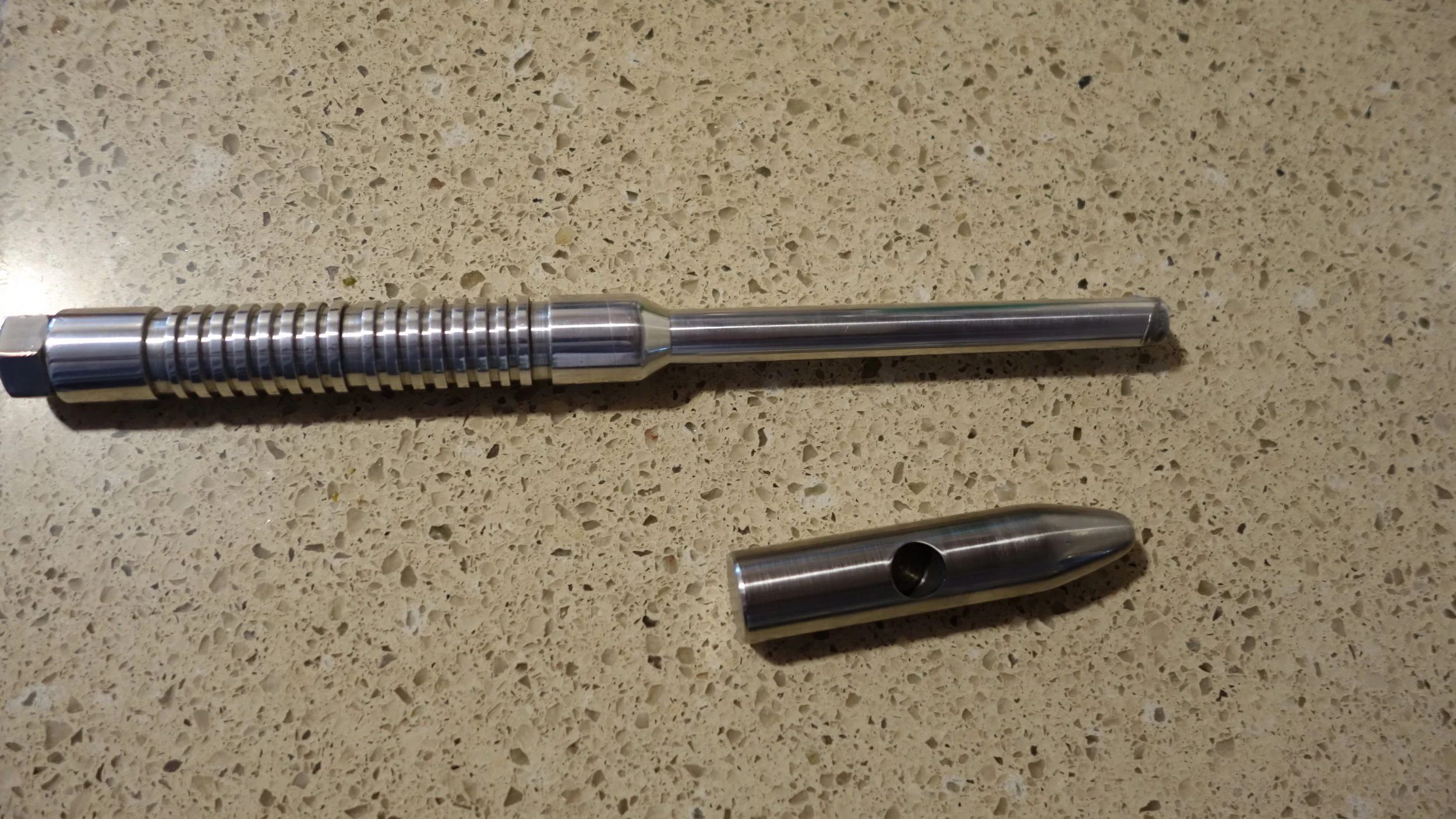
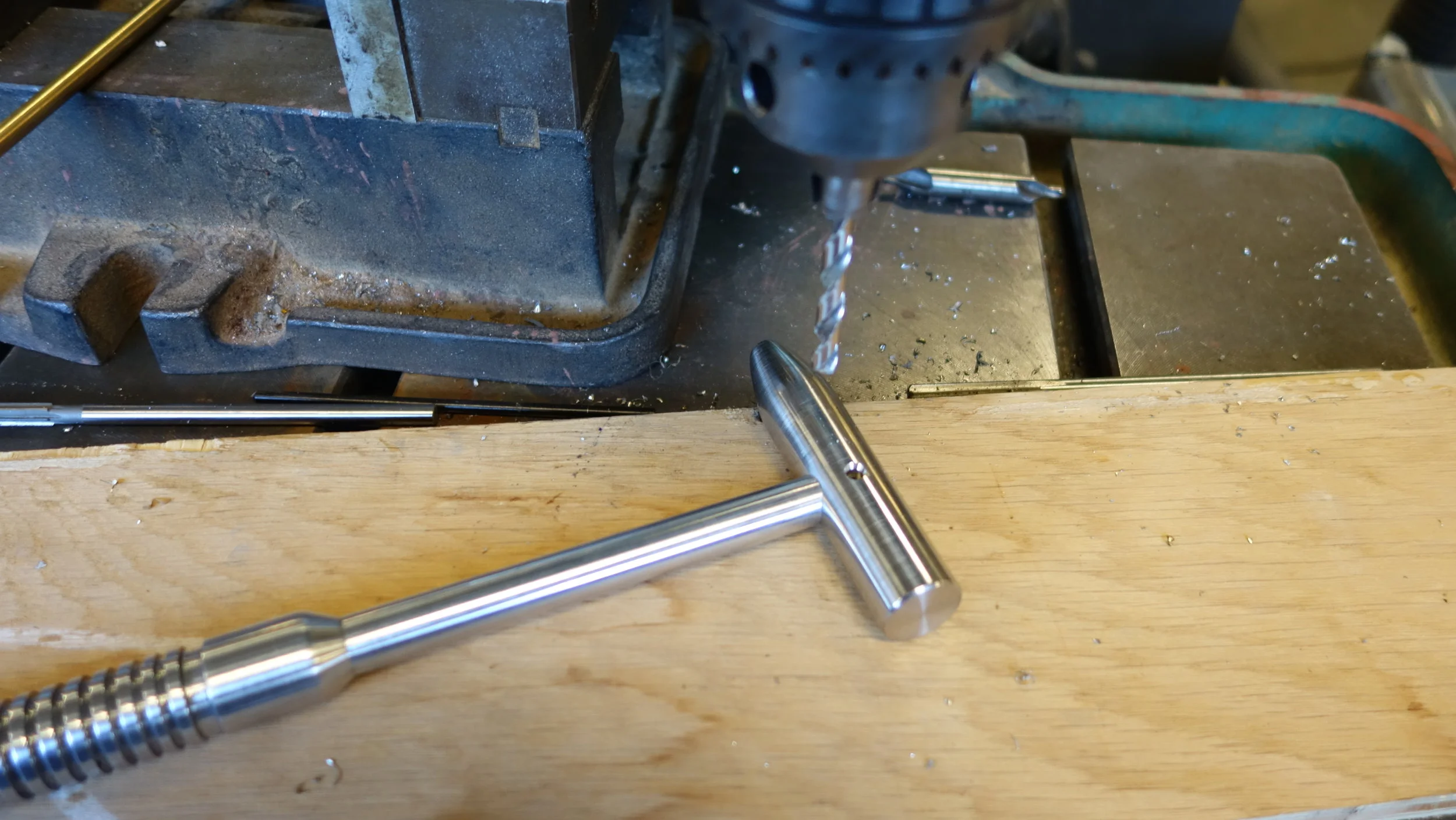
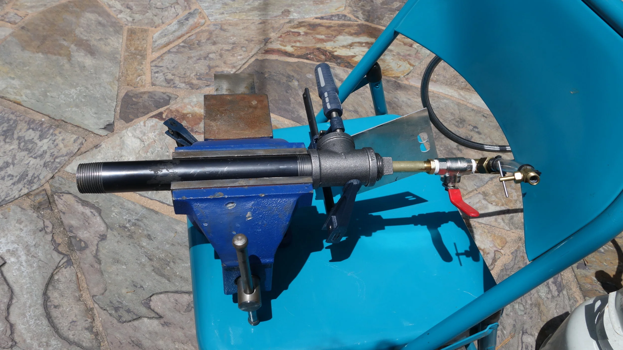
The control fin (see below) is actuated by a single servo, and has a 10 degree travel arc. This is sufficient for general locomotion, but would likely be insufficient for operation during the game. The fin pivots on two 1/4in steel dowel pins pressed into the motor mount and motion tower base. Both pins were heated and then inserted into nominal size holes. The fin’s pivot hole is 25 thou above nominal, and produced an adequate low friction fit after some working back and fourth.
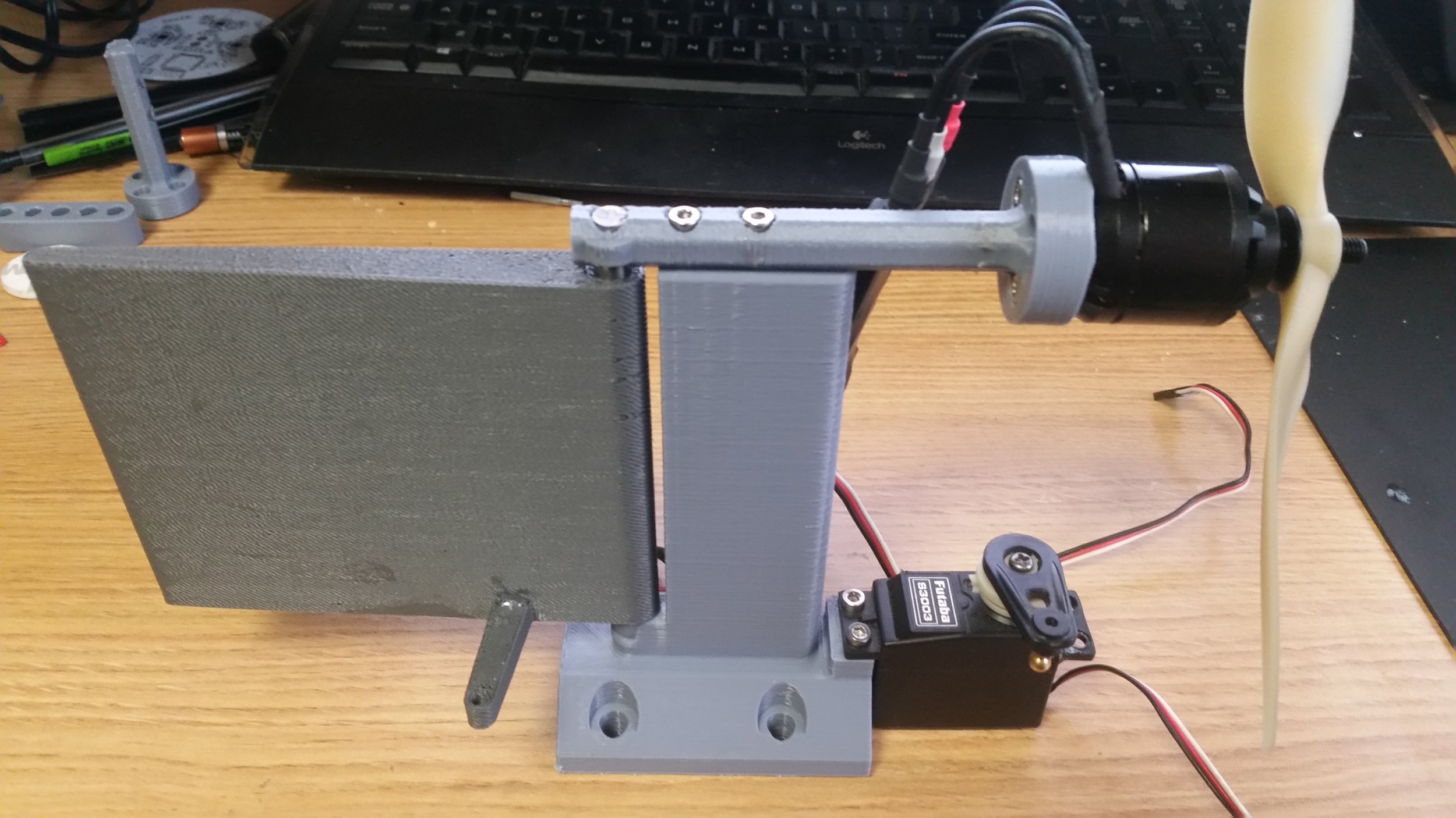
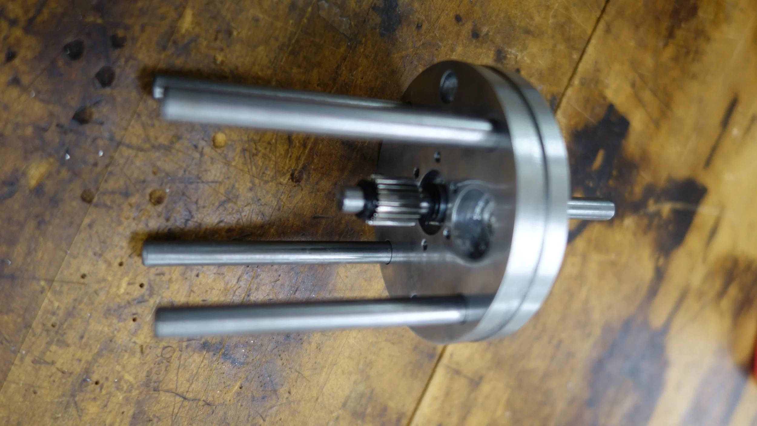
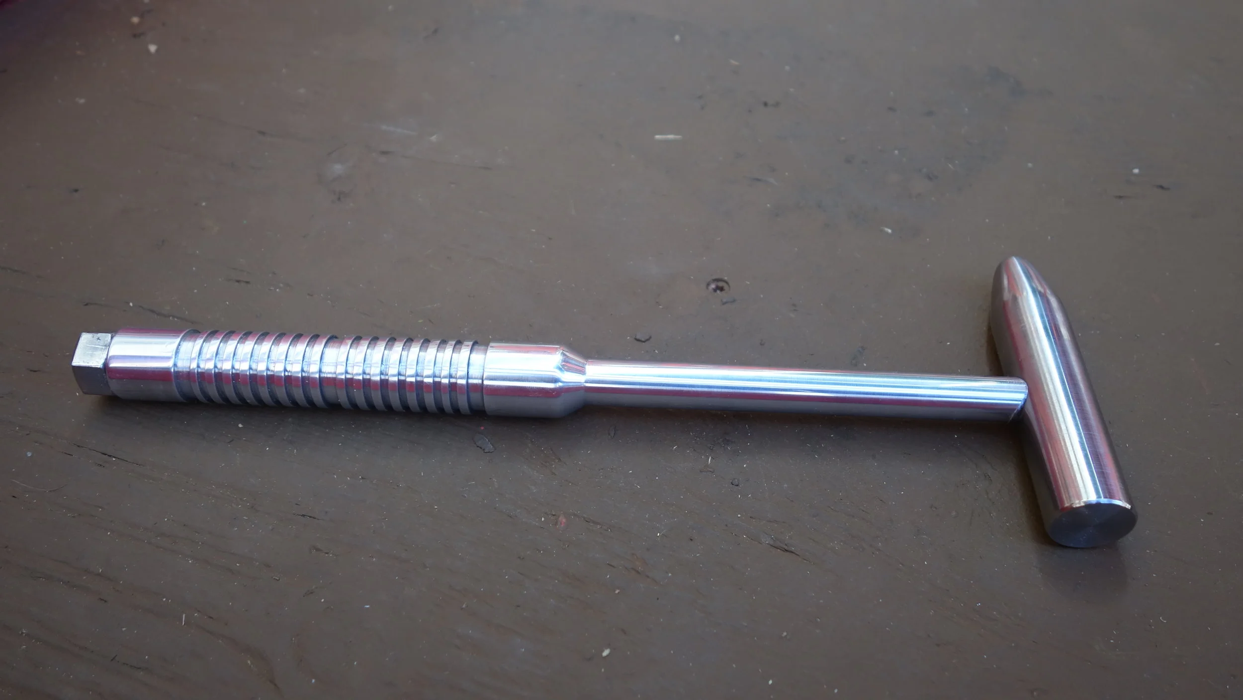
The thrust and control tower without linkages. Overall it performed well, with the sacrificial motor mount working as expected.

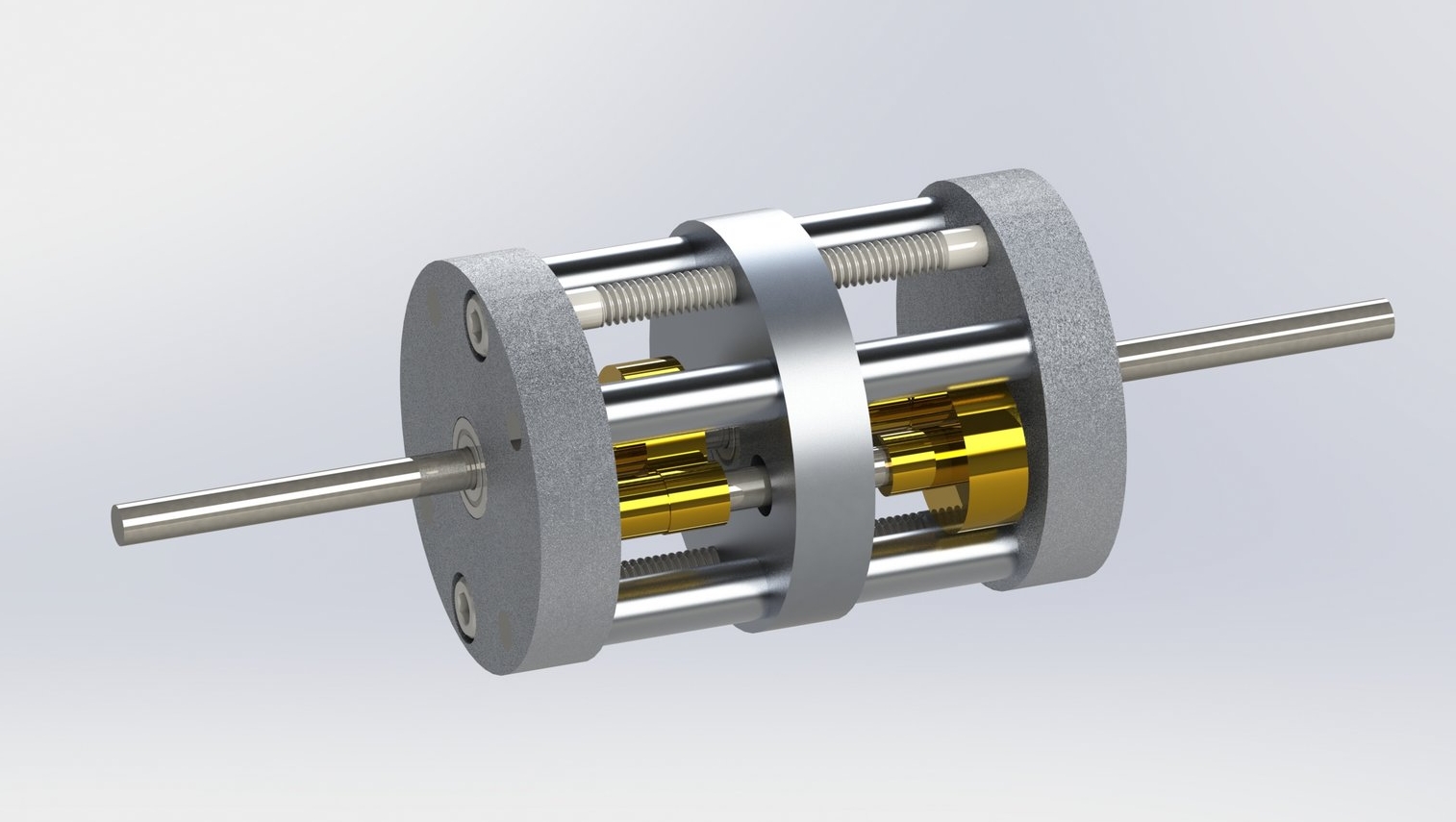
The completed assembly in Solidworks.
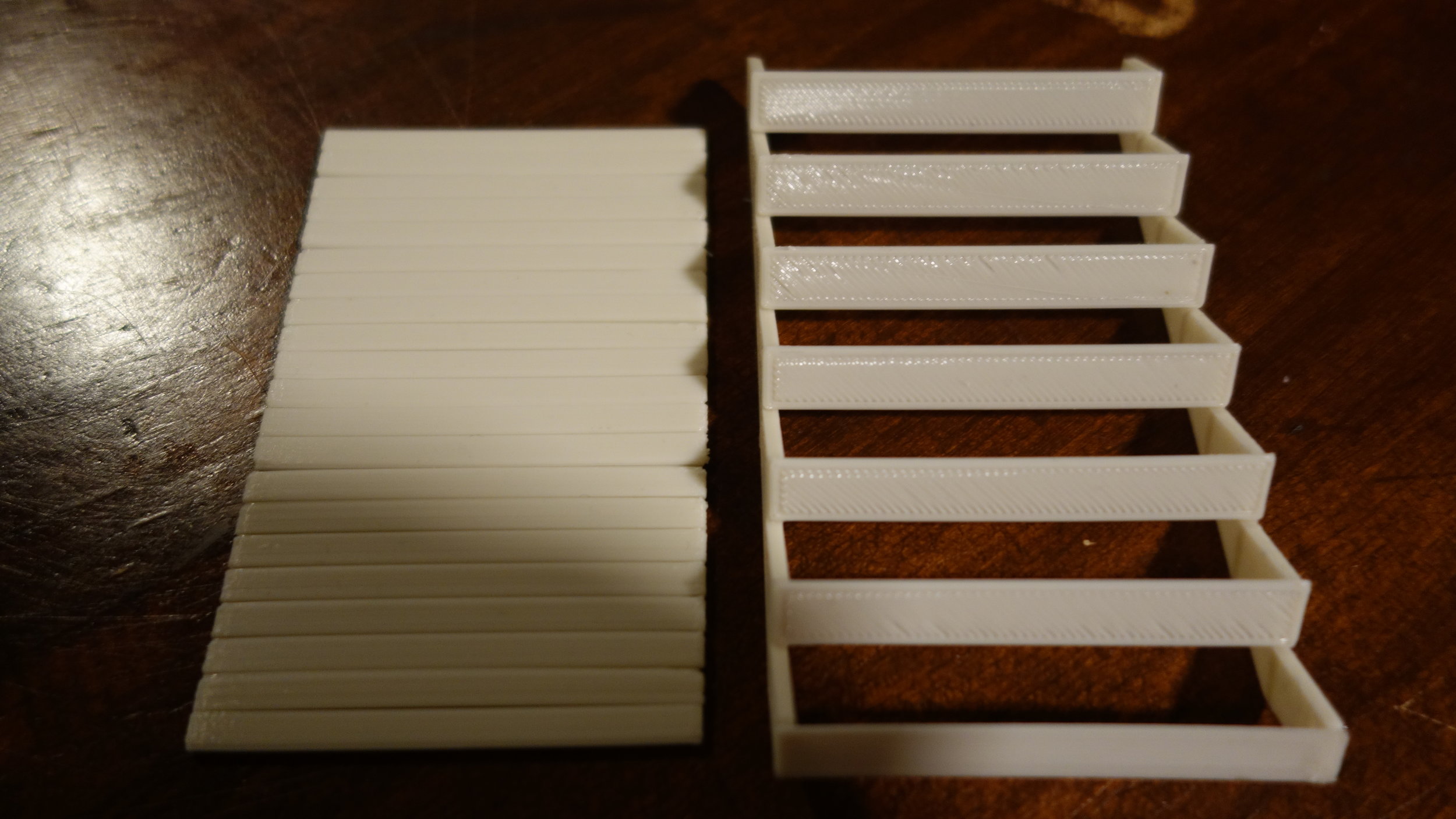
3D printed hull:
In the interests of time, and as a bit of an experiment, I decided to 3D print the entire hull as a single piece. This was largely successful, with a few fairly major caveats. The print took about 100 hours on one of the library’s CR10s. The lower hull was printed 5 layers thick, the deck was printed 3 layers thing, and the internal ribs were printed 2 layers thick. The boat was printed with layers perpendicular to the spine, with 105% flow and a perimeter speed of 30mm/s.

The first major issue I ran into was under-extrusion. Even running at 30mm/s, this print really pushed the CR10’s limits. As a result, the hull came out a lot weaker than I would have liked. Slowing down the print mid-way through helped, but seemed to deteriorate even more late-print. I am not clear on why, but plan to do some exploratory disassembly to find out.
The bigger issue, is that as a result, the boat leaks leaks like a cive. This was most pronounced in the early and late print where the under-extrusion was worst. Rather than printing a second hull, I decided to seal this one with spray paint. That required 4 general cotes across the whole hull, and 3-6 more in the worst areas. This fixed the leaking, thought it did nothing for the structural integrity of the hull more generally.
The control fin, motor mount, and thrust tower were printed without issue on my own machine.
Lessons:

3D printed parts cannot be assumed to be water-proof unless the filament is significantly (and consistently) over-extruded.
Spray paint makes a good sealant, but requires a large number of layers and has a poor $/in^2 ratio.
Slant sided, flat bottomed, hulls are very vulnerable to weight imbalance.
Project materials:
Solidworks: [CLICK HERE]
STLS: [CLICK HERE]