Flame Thrower

Summary:

Roasting marshmallows with the torch. I thought this worked rather well, though folks who prefer their marsh mellows more browned and less crispy might disagree.

Roasting marshmallows with the torch. I thought this worked rather well, though folks who prefer their marsh mellows more browned and less crispy might disagree.

This flame thrower was a marvelous one-day-build, created with the fantastic Emma Kerr, for an icecream and marshmallows party later the same day.

It uses Sterno butane canisters as the main fuel source and an olive oil lamp as the pilot light. The calk gun is used to release butane from the canister onto the pilot light where it ignite. I particularly like this design, because it can be created entirely from home depot parts, and requires only a torch and drill to fabricate.

Note: This project, like all fire projects, was operated on private property with the permission of the owners. Appropriate PPE and fire suppression equipment are very important if you plan a similar build.

The front of the torch is an oil lamp. This is made a 90 degree bend, and a short length of copper pipe sealed at one end. I have found that olive oil and Tiki oil both work well, although the Tiki oil does light better. It is important that the sol…

The front of the torch is an oil lamp. This is made a 90 degree bend, and a short length of copper pipe sealed at one end. I have found that olive oil and Tiki oil both work well, although the Tiki oil does light better. It is important that the soldered connection between the bend and the reservoir be well sealed for obvious reasons. If possible the wick should bend into the reservoir, but it works fine with just a short length in the 90 degree section.

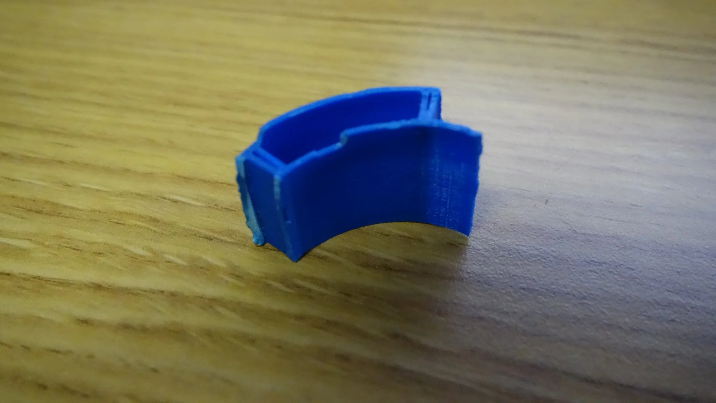
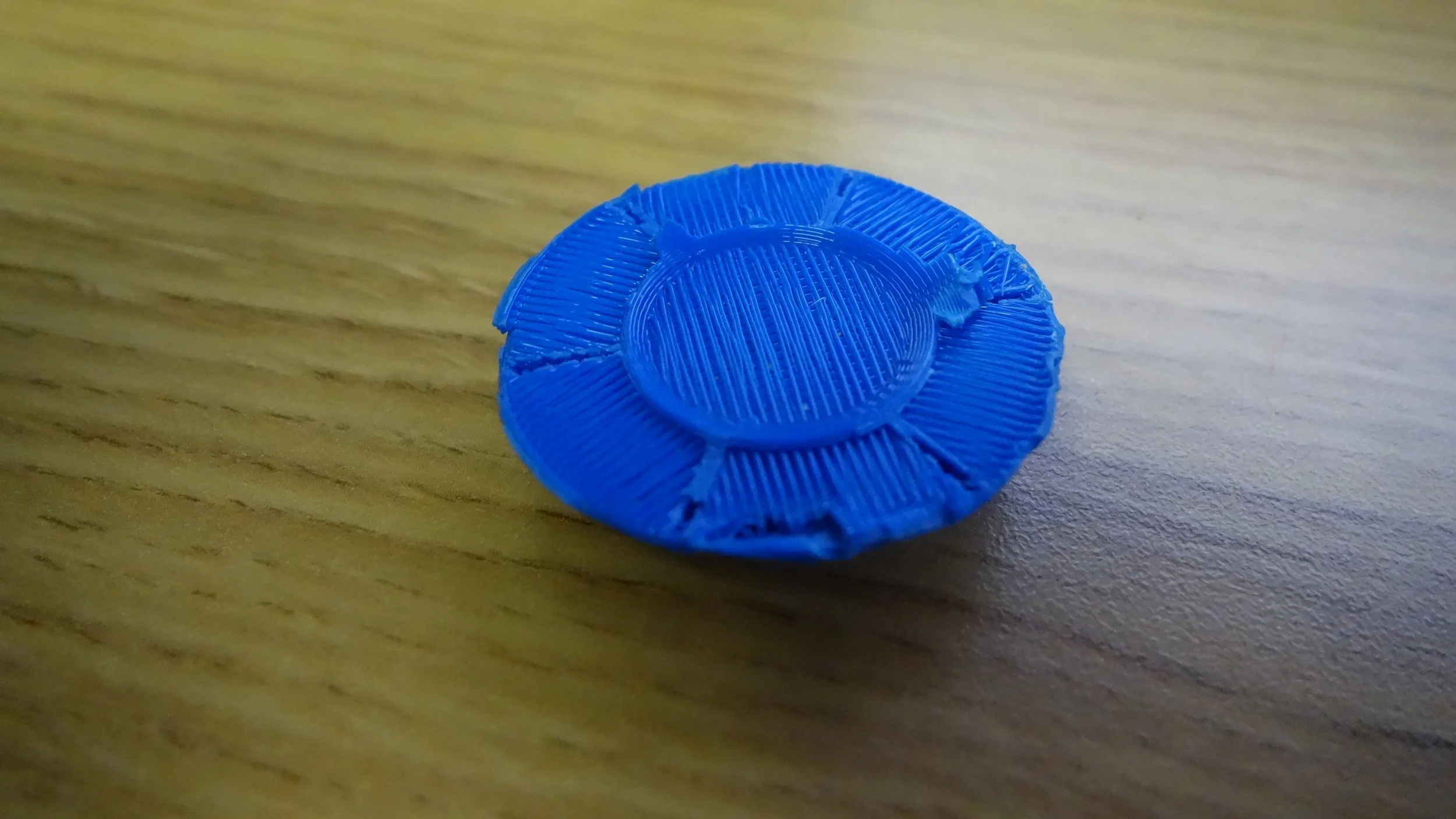
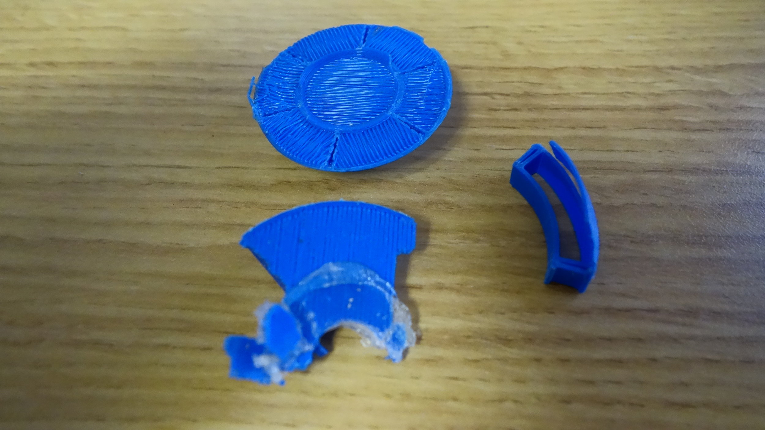
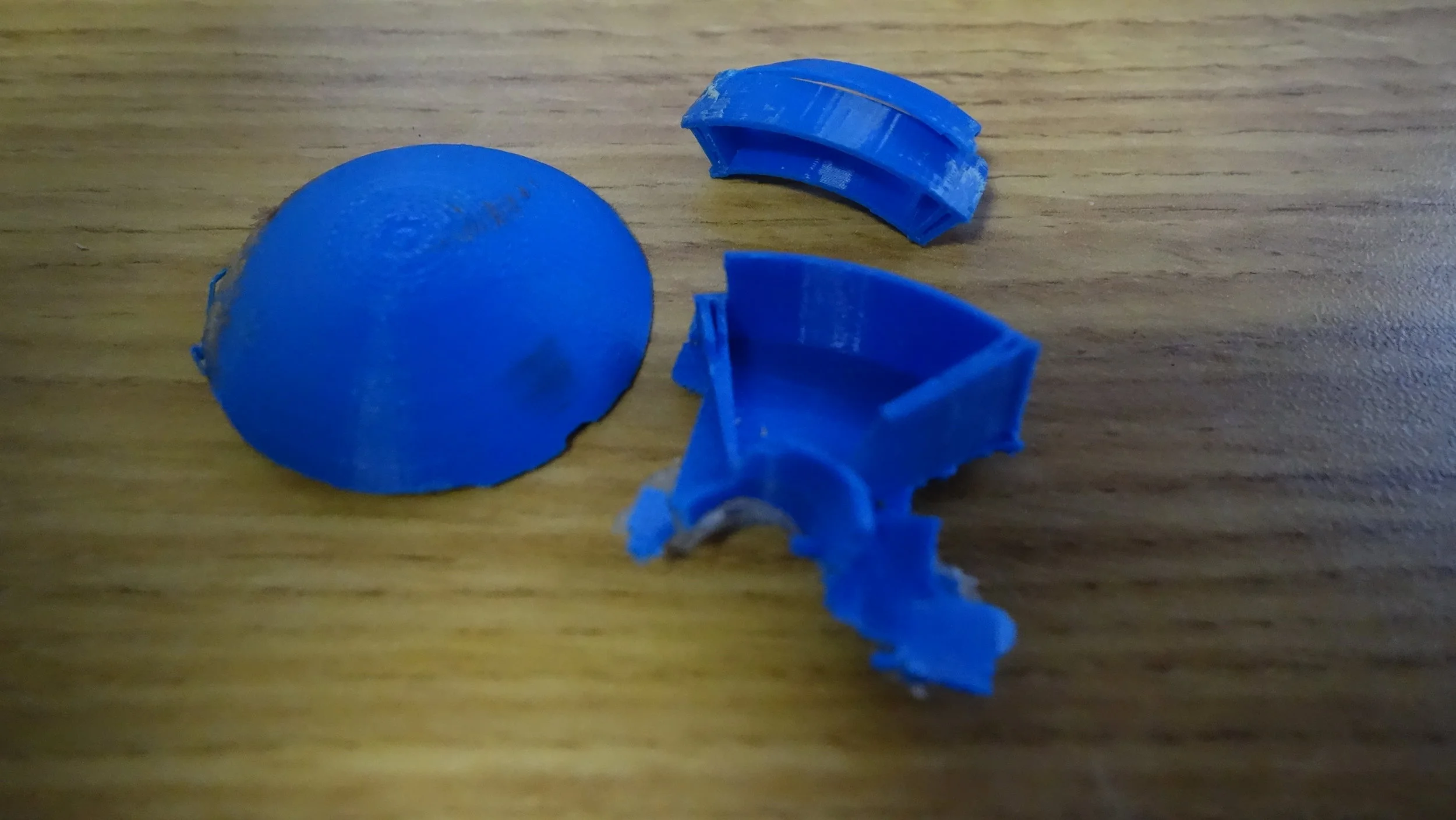
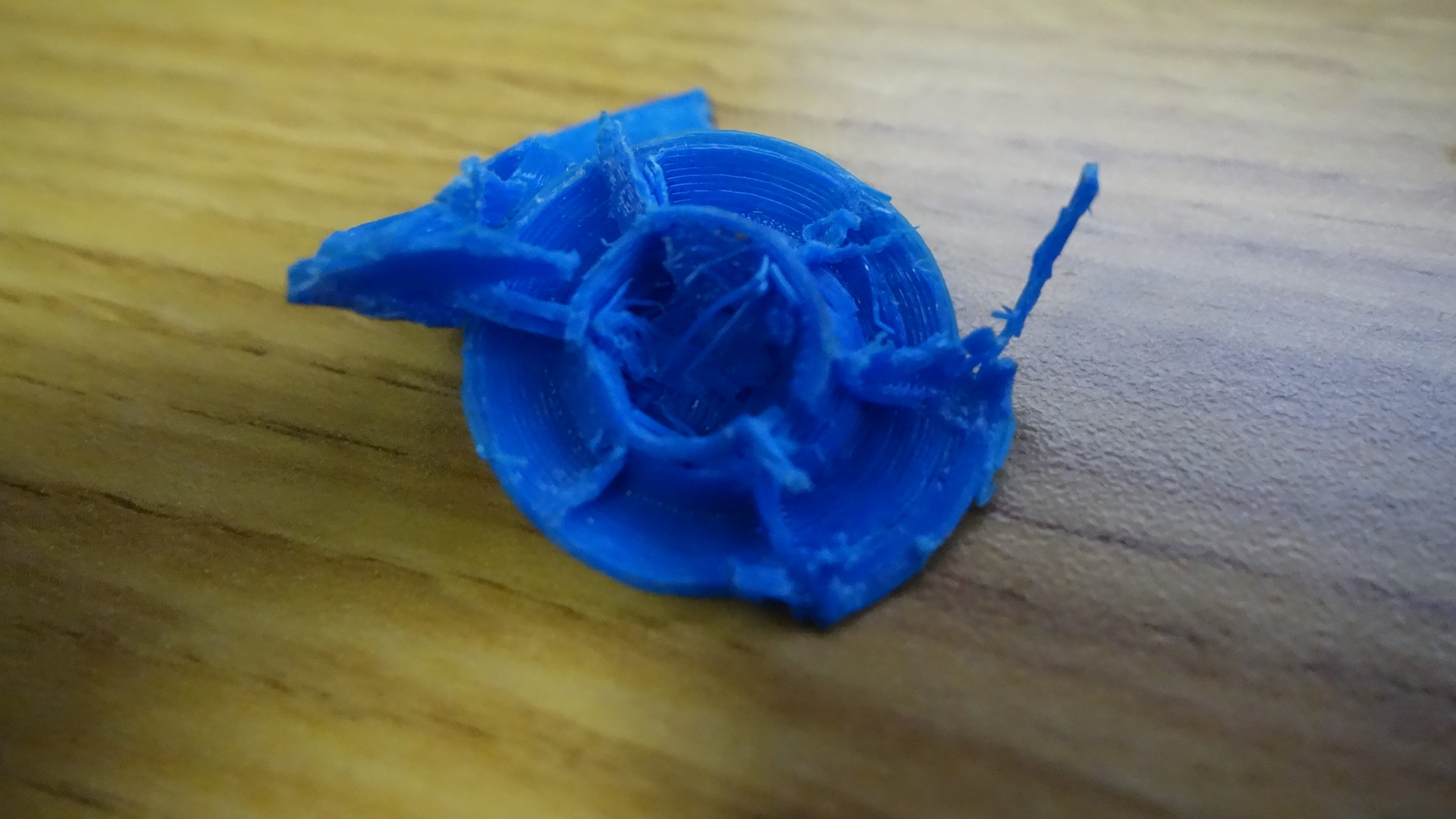
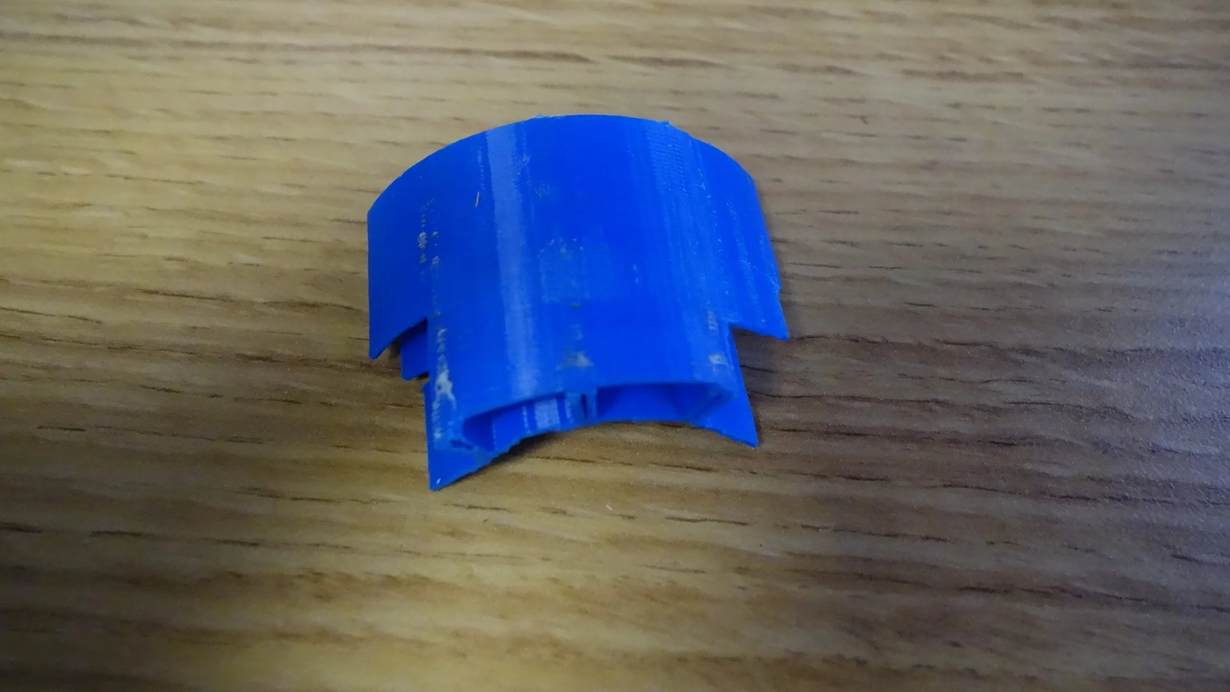
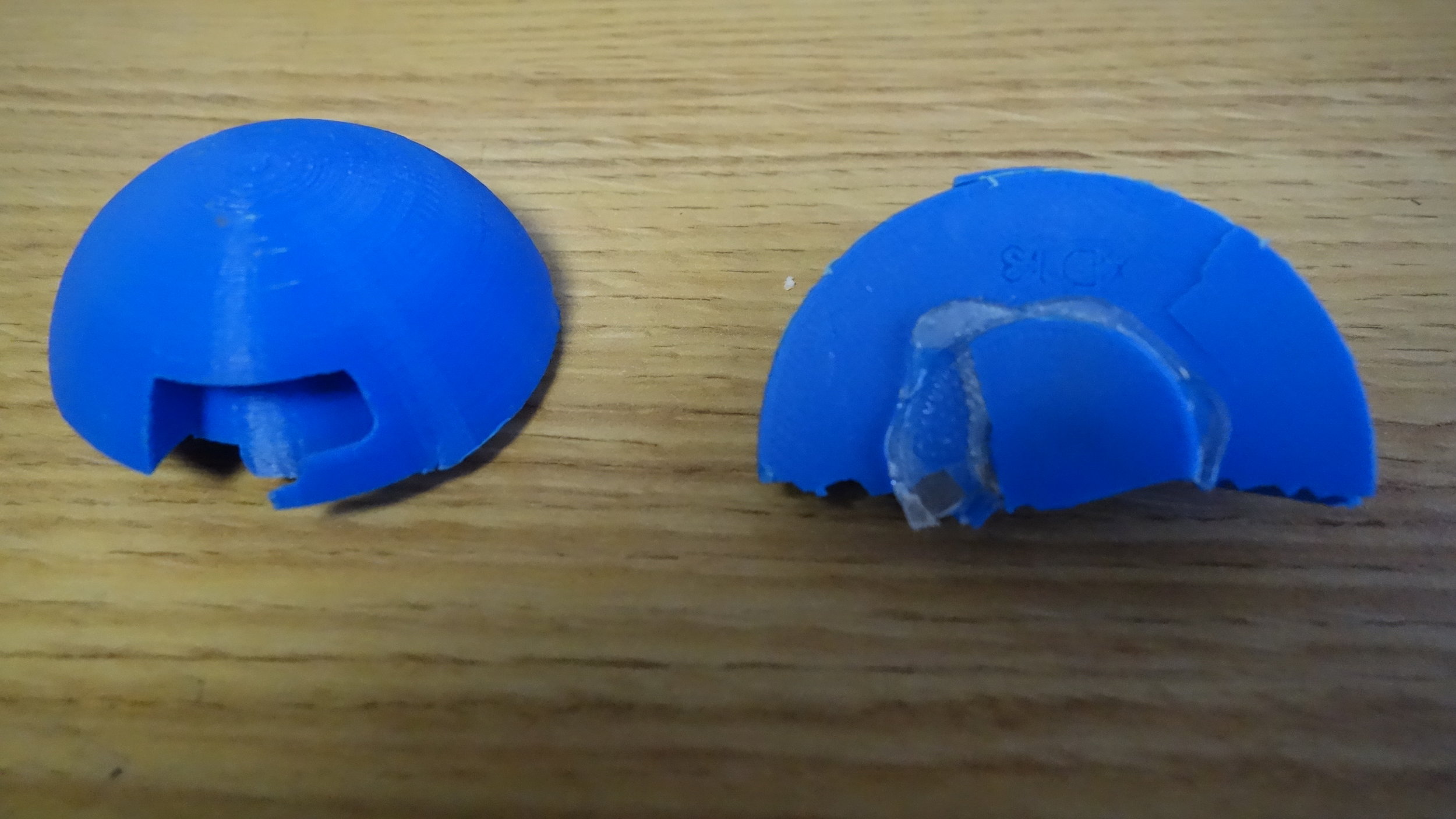
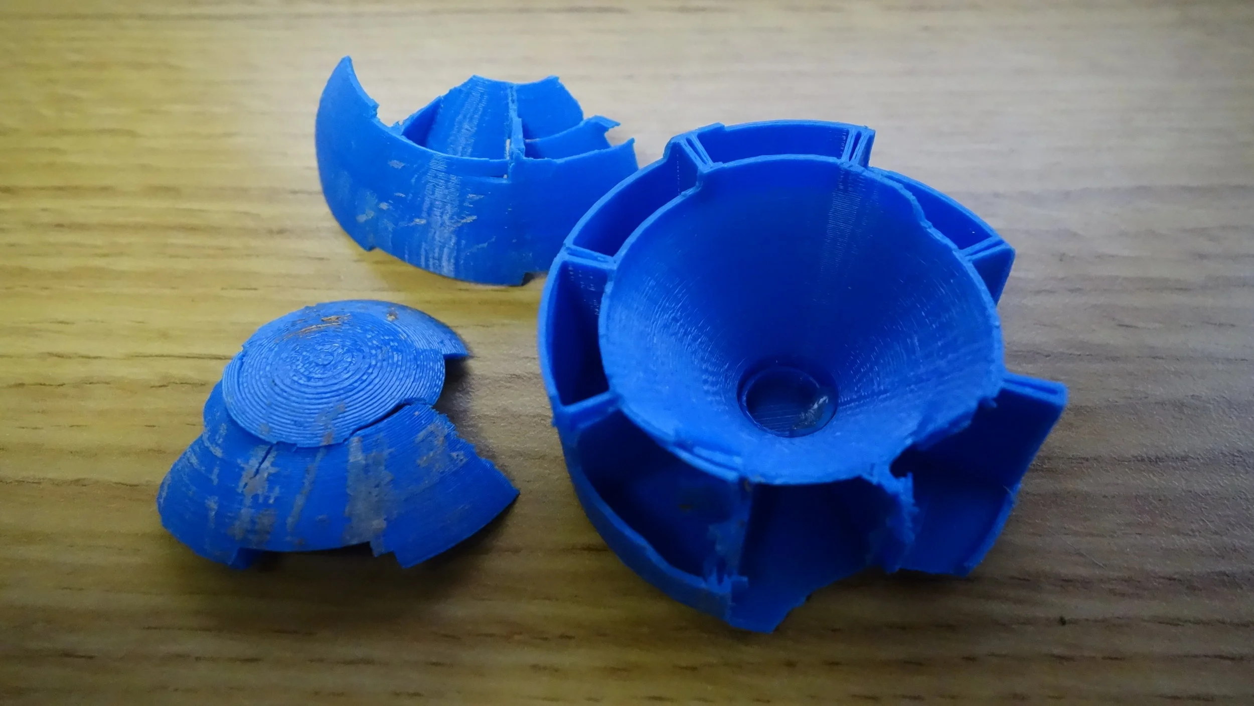
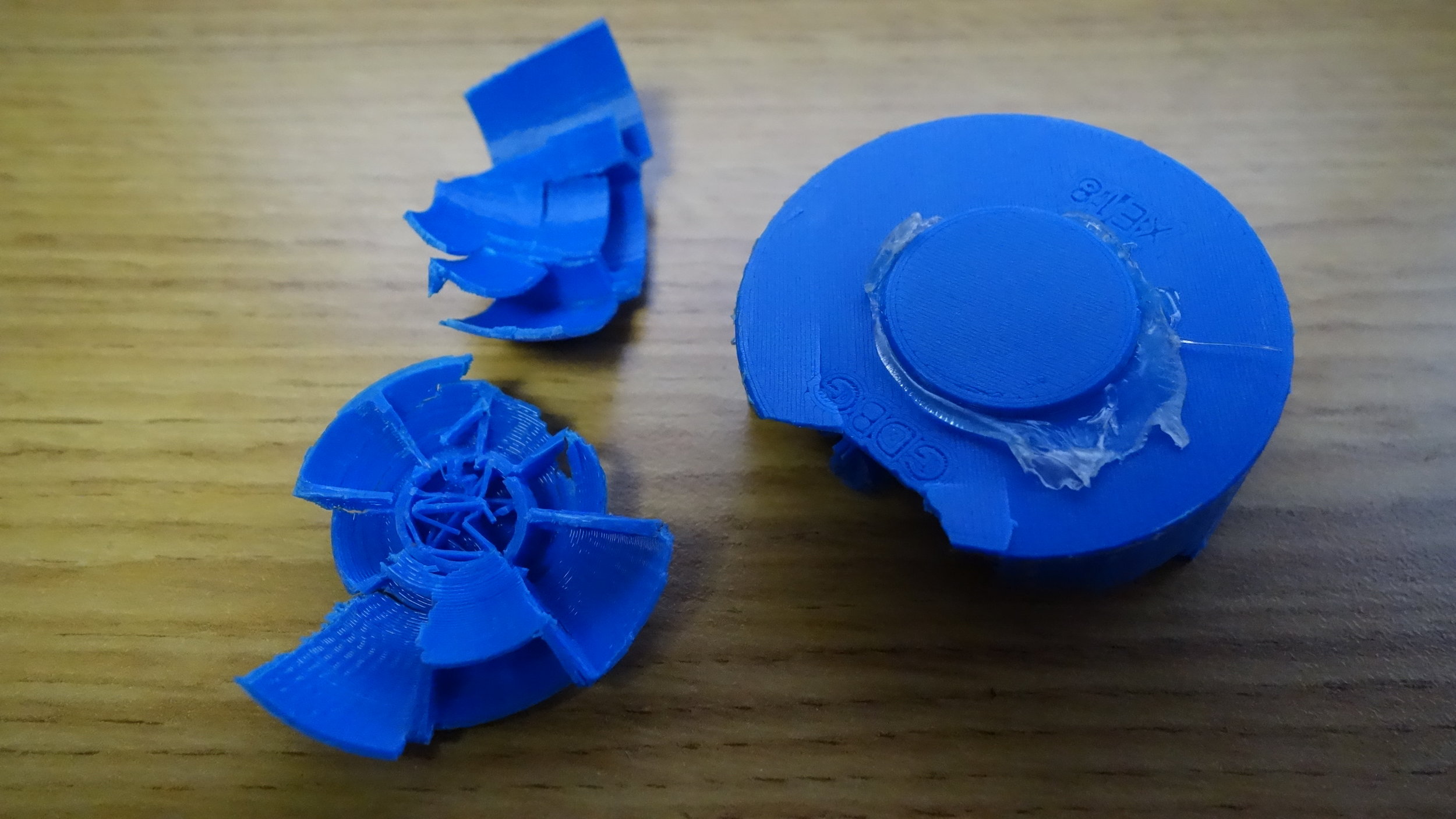
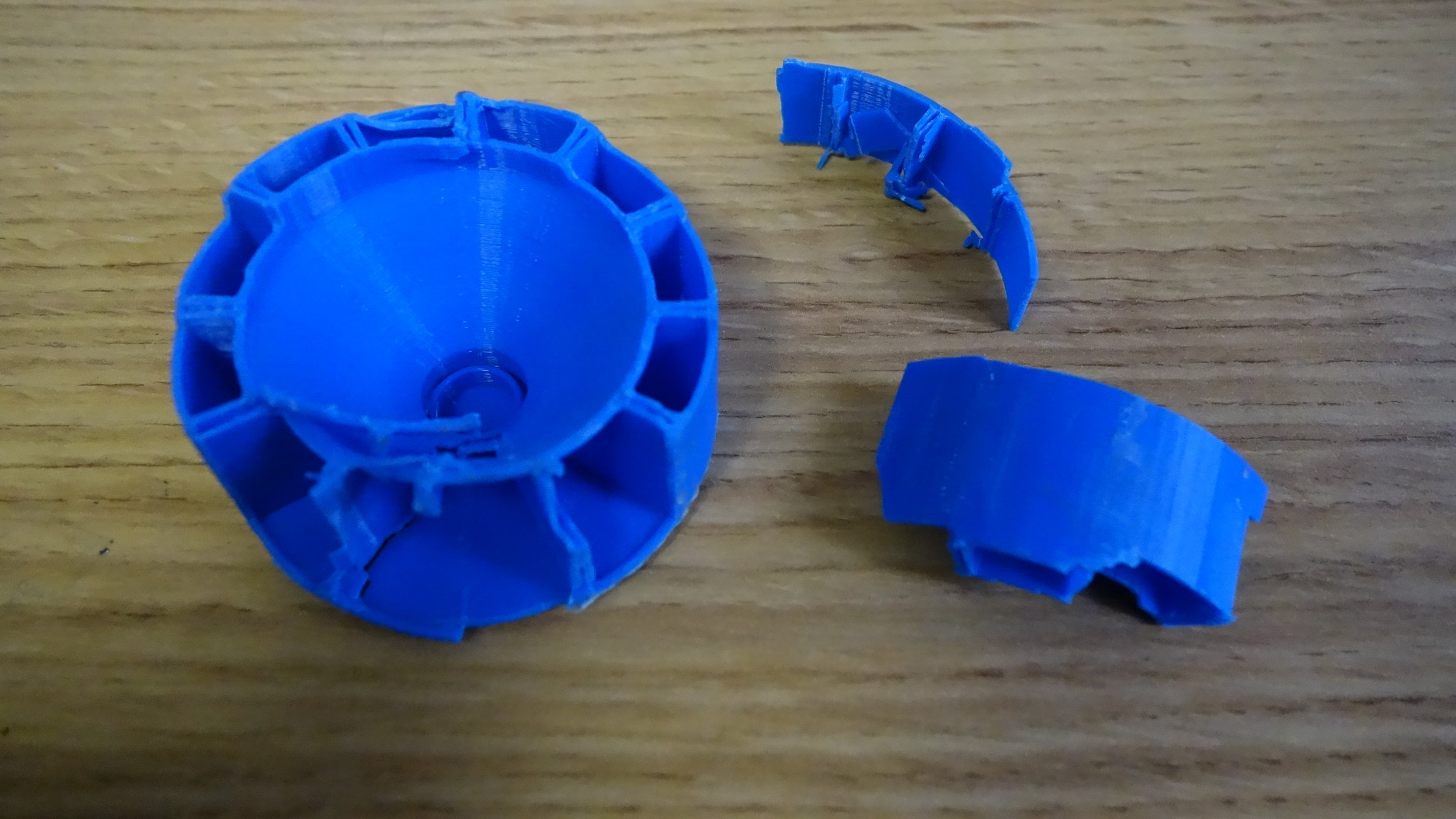
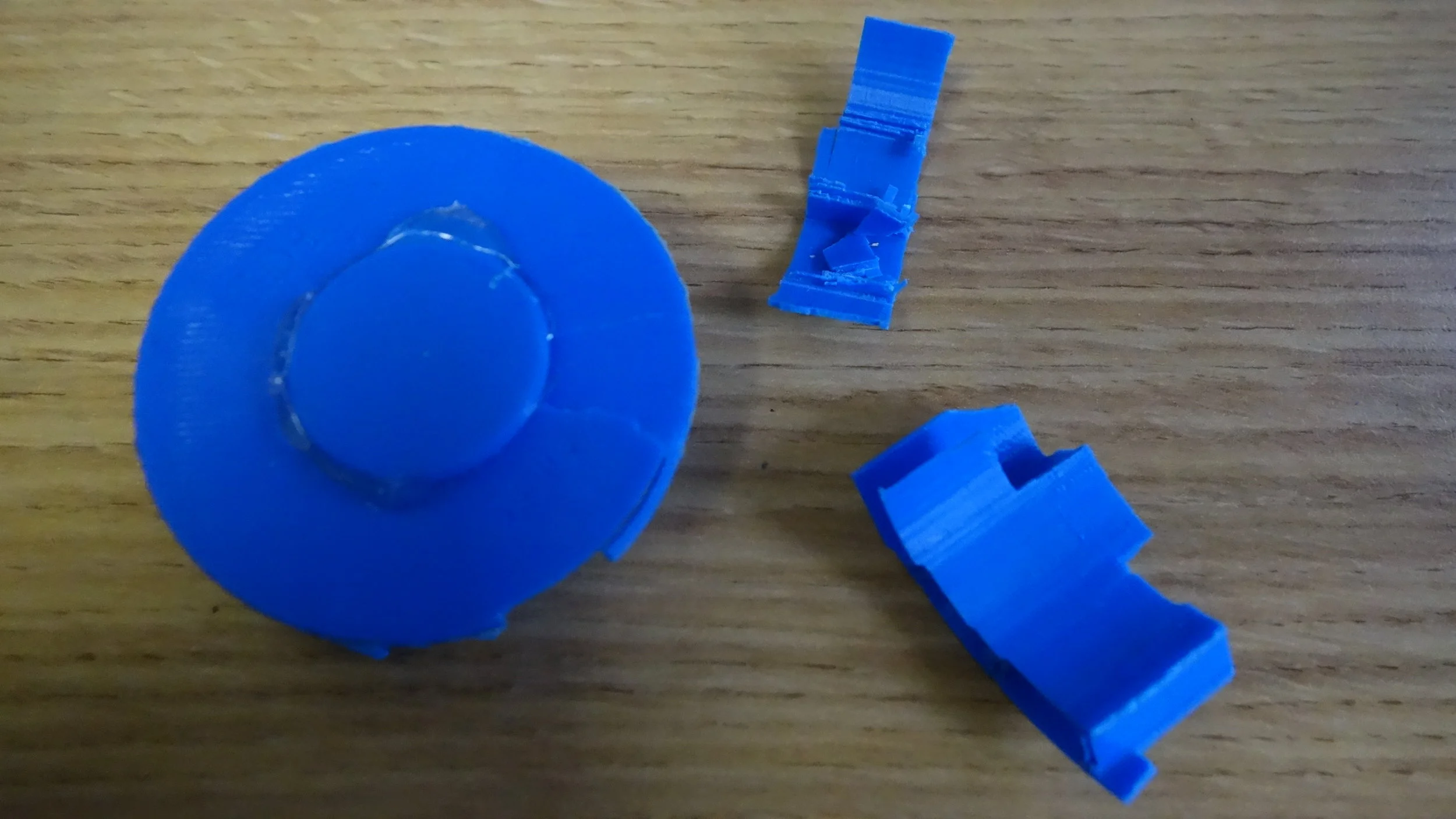
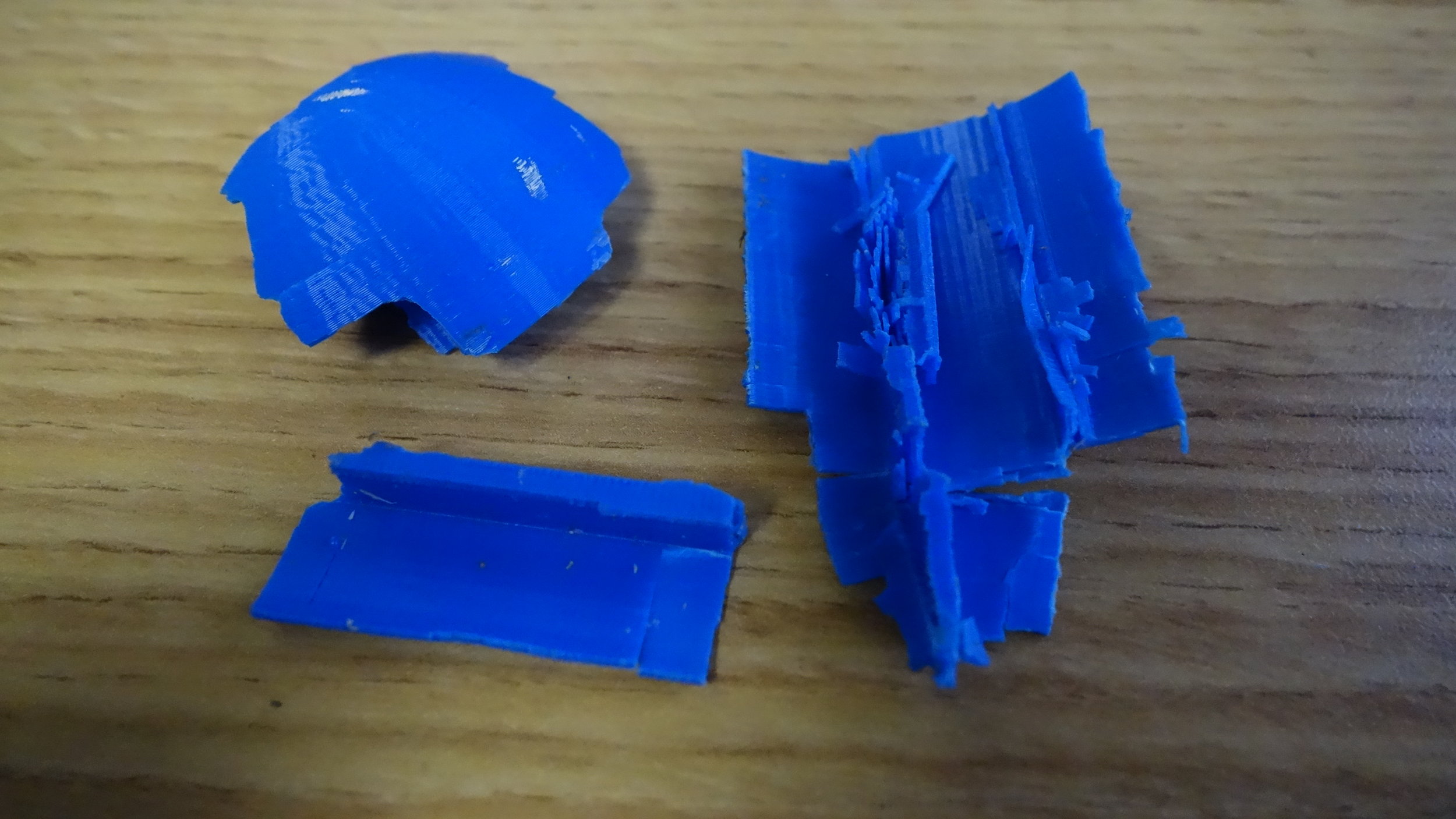
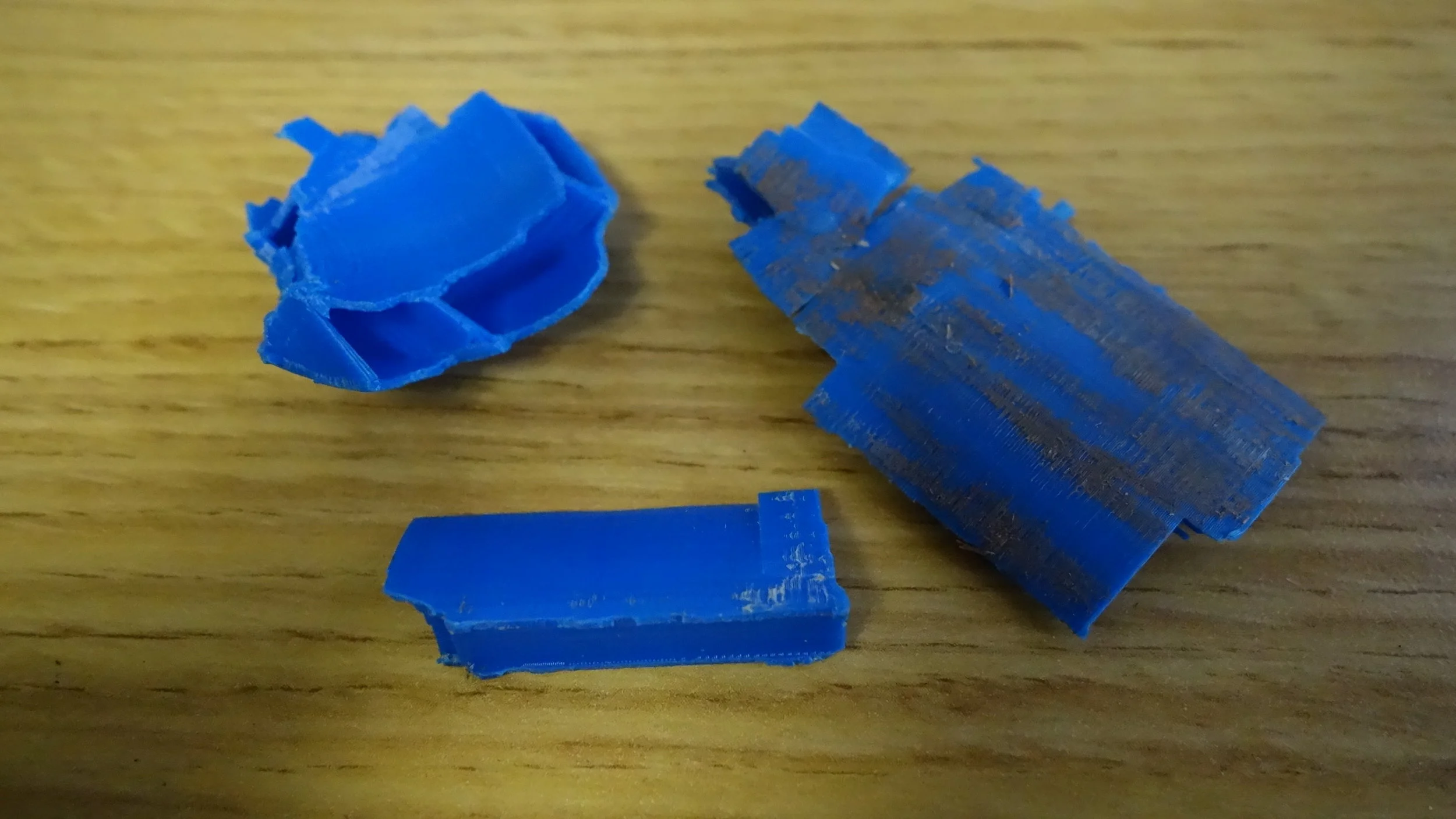
I used a 3D printed disk with a double tapered hole as the output. This works well, but is fundamentally a consumable part (Order of 3 canisters before change). The main issue that it can slightly impede the flow of butane and that when this happens…

I used a 3D printed disk with a double tapered hole as the output. This works well, but is fundamentally a consumable part (Order of 3 canisters before change). The main issue that it can slightly impede the flow of butane and that when this happens the disk tends to melt a bit when the fire goes out. This can be solved either by using an aluminum disk, or by changing to a fuel type that has a tapered tip. With that said, I am pretty happy with this as a consumable for now.

The forward handle is connected to the rest of the frame by a t-joint. Placing the forward handle slightly before the nozzle outlet provides a lot of control, but does mean welding gloves are more or less mandatory for operating the thrower two hand…

The forward handle is connected to the rest of the frame by a t-joint. Placing the forward handle slightly before the nozzle outlet provides a lot of control, but does mean welding gloves are more or less mandatory for operating the thrower two handed.

The handle and pilot assembly is connected to the chalk gun by two 4-40 socket head cap screws running from inside the chalk gun assembly to tension nuts on the underside of the pipe. I was surprised to discover that this proved more than adequate e…

The handle and pilot assembly is connected to the chalk gun by two 4-40 socket head cap screws running from inside the chalk gun assembly to tension nuts on the underside of the pipe. I was surprised to discover that this proved more than adequate even without additional supports.

For the pilot wick I use a standard Tiki lamp wick. I’ve found this works well with a variety of fuels, plus they are available pretty much everywhere.

For the pilot wick I use a standard Tiki lamp wick. I’ve found this works well with a variety of fuels, plus they are available pretty much everywhere.

Steel rails, installed after painting, help ensure that the canister is able to move smoothly when actuated. Although these are not strictly required for the device to work, I do find that they considerably improve reliability

Steel rails, installed after painting, help ensure that the canister is able to move smoothly when actuated. Although these are not strictly required for the device to work, I do find that they considerably improve reliability

Depending on the exact build, it may be a good idea to bypass the ratcheting mechanism near the operation point of the thrower. This prevents it from ratcheting into a permanently “on” position. Filing the teeth of a short length of the plunger arm …

Depending on the exact build, it may be a good idea to bypass the ratcheting mechanism near the operation point of the thrower. This prevents it from ratcheting into a permanently “on” position. Filing the teeth of a short length of the plunger arm seems to accomplish this nicely.

Crawler Superstructure Assembly

The autonomy package, removed from Balto immediately prior to shipping.

The autonomy package, removed from Balto immediately prior to shipping.

Summary:

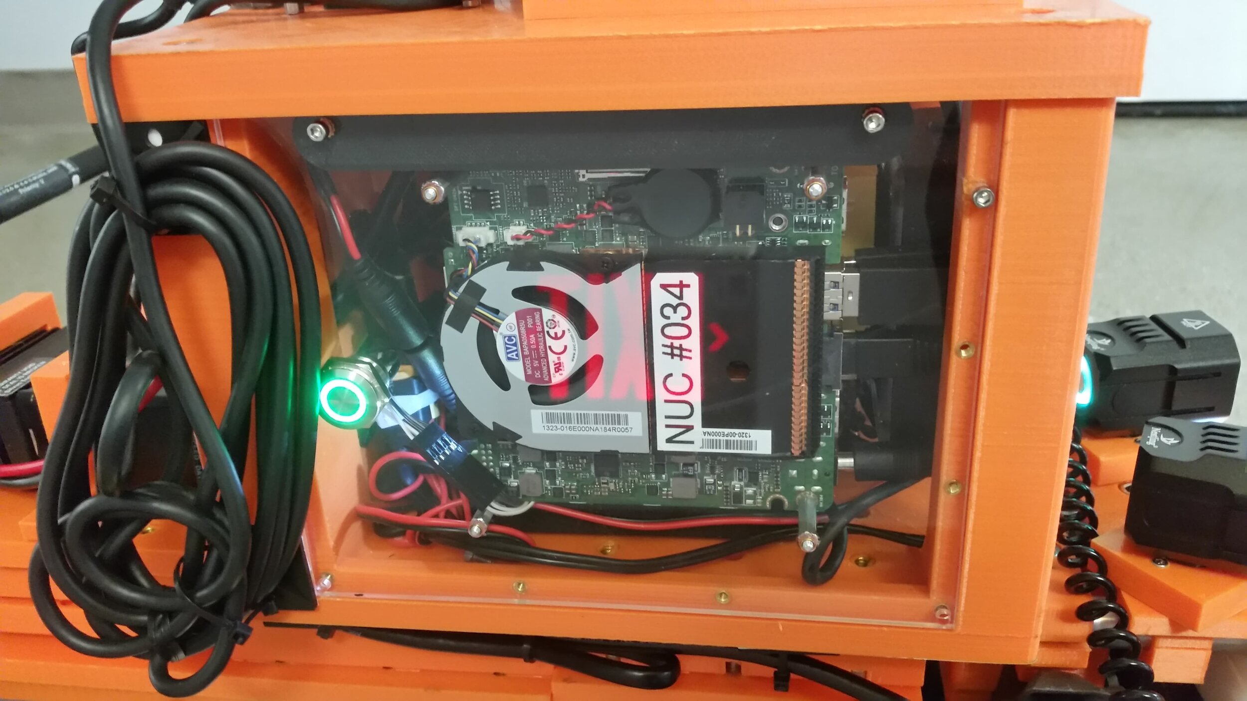
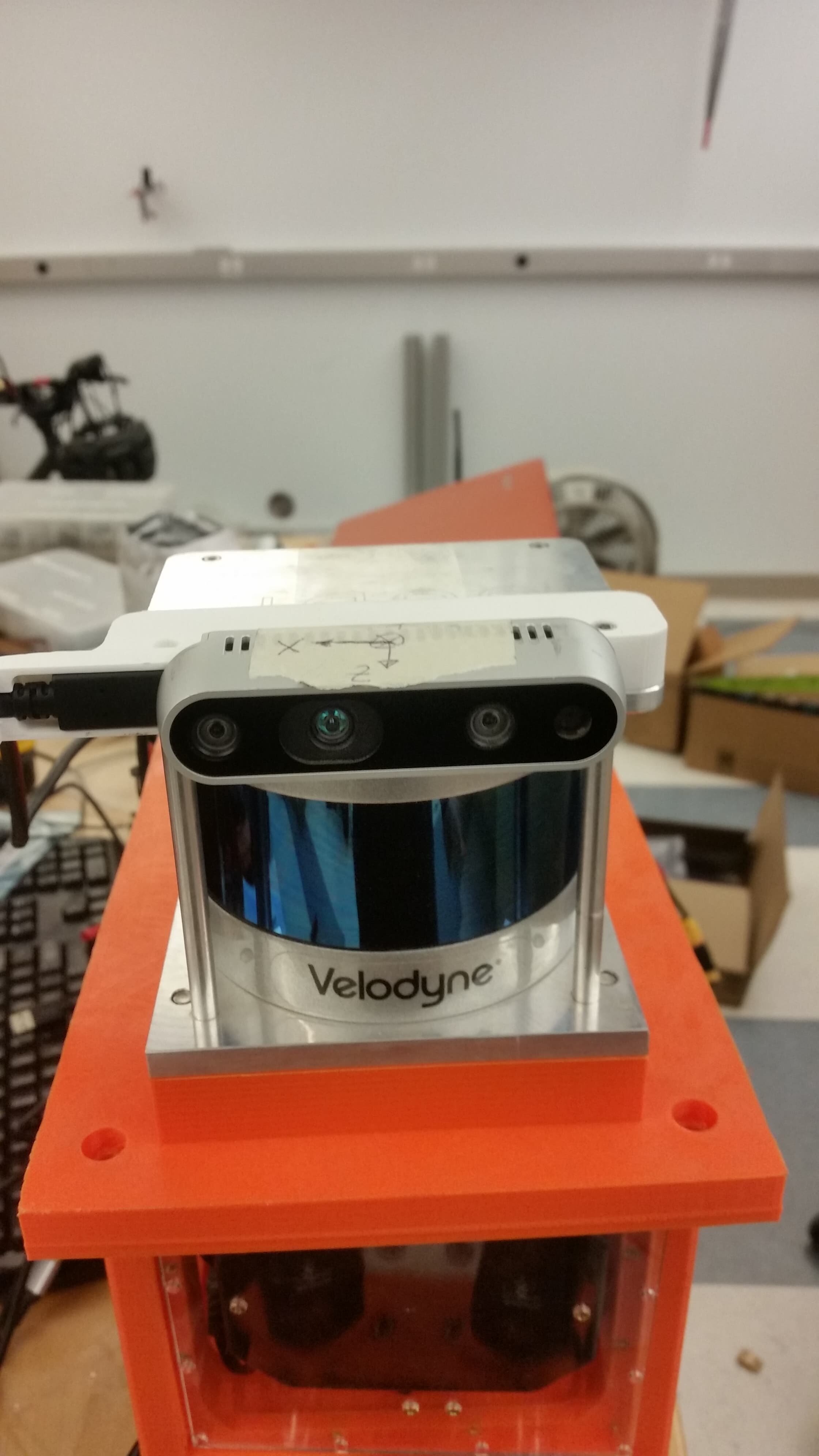
The compute housing holds the NUC, Velodyne box, TX2, router and Ethernet switch. This is the first integrated version of the housing where all of the components are in one enclosure. It is designed to be dust and splash resistant with interchangeable laser cut panels for easy access to the internals. This is the housing that we used on Balto when it ran in the tunnels circuit.

The housing itself is composed of three printed parts, and three laser cut panels. The printed parts should be printed with thick walls, and take a combined 40 hours on a crafbot plus at medium printing speeds. The three laser cut panels are designed to 3D printable if need be, though using a laser does allow for nice graphics.

This version of the electronics housing was completed in just over a week and, although I like it on the whole, there are still a lot of modifications I want to make. In particular to do with weight distribution and water resistance. With that in mind, I have chosen to include a slideshow of assembly photos rather than a full build log. If you are building up this version (and to be clear I do like it rather a lot) definitely feel free to reach out and I can provide you with more detailed instructions.

Favorite Elements:

This design had a few elements that I felt worked particularly well.

  • NUC Switch - From a purely aesthetic standpoint, the NUC’s power switch is definitely my favorite part of the housing. It’s got a green led ring very reminiscent of a lightsaber, and mounts nearly flush to the outer panel. On a practical note it is both easier and more water resistant than just having a hole to use the built in one.

  • Acrylic panels - Using acrylic wall panels let us iterate the mounting design much faster than if we had been using printed panels. They are also clear which is nice for checking that all’s well. The panels are still designed so they can be printed if the laser ever goes down.

  • Velcro - Our original design had everything mounted with screws. Using velcro for some of the lighter weight parts made it much easier to assemble and disassemble things during the debug phase.

  • Waterproof wire outlet - Using a compressed foam sandwich to pass cabling into and out of the box worked perfectly. It’s easy to install and remove, but also virtually splash proof.

  • Aluminum reinforcement - Using aluminum reinforcement rods to help prevent de-lamination seems to have worked. Although we haven’t yet had any highly energetic crashes.

Areas for improvement:

This version of the housing worked well, but it was designed in a short period of time and there is certainly room for improvement. A few particularly notable shortfalls can be found below:

  • Weight - The NUC, Velodyne, and Velodyne converter are all above the flying bridge. This results in a dangerously high center of mass. Addressing this will likely require a full redesign, but remains a top priority.

  • Dust - The lack of filters means dust can build up in the system over time. Was not an issue for short-term operations, but could become an issue over multiple days or weeks of testing.

  • Access - The system currently requires removing about 8 screws to address any wiring problems. Not bad, but certainly less convenient than say snaps or clamps. The top is 1/4-20 while the sides are 4-40 which I also do not love.

  • Screws - We currently use both 3/8 and 1/4 length 4-40 socket head cap screws. Switching to just the 3/8 would require minimal modifications and would improve the assembly process.

  • Heat - Under certain operating conditions it might be possible for the TX2 or NUC to overheat when running full out. We did not experience this at competition, but better thermal management remains a priority.

  • Power - A more considered plan for power distribution and regulation would improve reliability and reduce the risk of accidental damage during assembly.

Build Photos:

The housing base and lid. The two pieces interface securely with a 45 degree chamfer and are held together by the 4 1/4-20 screws. This setup worked well and was very robust in practice, I would use it again.

The housing base and lid. The two pieces interface securely with a 45 degree chamfer and are held together by the 4 1/4-20 screws. This setup worked well and was very robust in practice, I would use it again.

The upper us hub was held into a 3D printed mount using Velcro.

The upper us hub was held into a 3D printed mount using Velcro.

The aluminum rods were cut to length and then installed with a drill to help ream out the hole. CA glue, or epoxy should be added to fight laminant failures. If spinning the rods proves insufficient then grinding a separate rod with a d-bit tip will…

The aluminum rods were cut to length and then installed with a drill to help ream out the hole. CA glue, or epoxy should be added to fight laminant failures. If spinning the rods proves insufficient then grinding a separate rod with a d-bit tip will help.

We were unable to get the correct size of header shipped in time, so we soldered our switch extender directly onto the NUC. (You can see the hole we used to use for poking the onboard button.

We were unable to get the correct size of header shipped in time, so we soldered our switch extender directly onto the NUC. (You can see the hole we used to use for poking the onboard button.

The button side of the connector. It is connected white to white and black to black so that the button and LED go to the correct parts of the header.

The button side of the connector. It is connected white to white and black to black so that the button and LED go to the correct parts of the header.

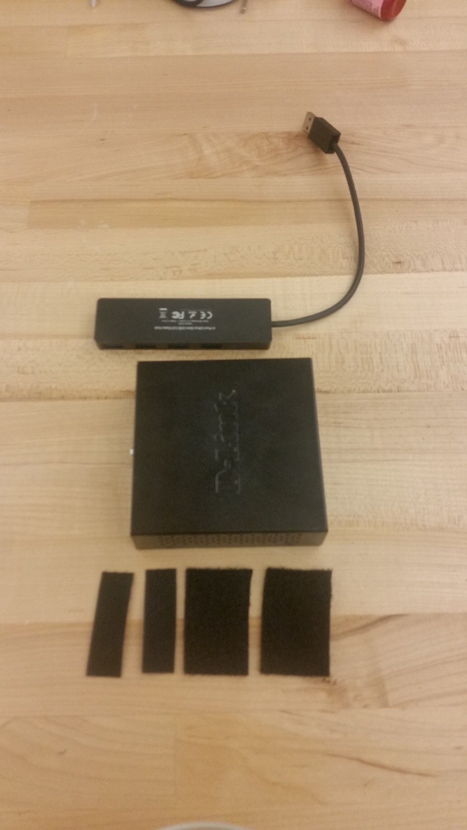
Velcro was used for holding down the D-Link, TX2, and lower USB switch.

Velcro was used for holding down the D-Link, TX2, and lower USB switch.

The lower USB switch and D-Link were Vecro’d together, and then Velcro’d to the floor of the housing.

The lower USB switch and D-Link were Vecro’d together, and then Velcro’d to the floor of the housing.

The TX2 was first mounted on a 3D printed plate with standoffs.

The TX2 was first mounted on a 3D printed plate with standoffs.

All of the various components fit with a bit of room to spare (though not much).

All of the various components fit with a bit of room to spare (though not much).

Crawler ODrive housing

Summary:

Our first Odrive housing, installed on the underside of the flying bridge without the venting flue.O

Our first Odrive housing, installed on the underside of the flying bridge without the venting flue.O

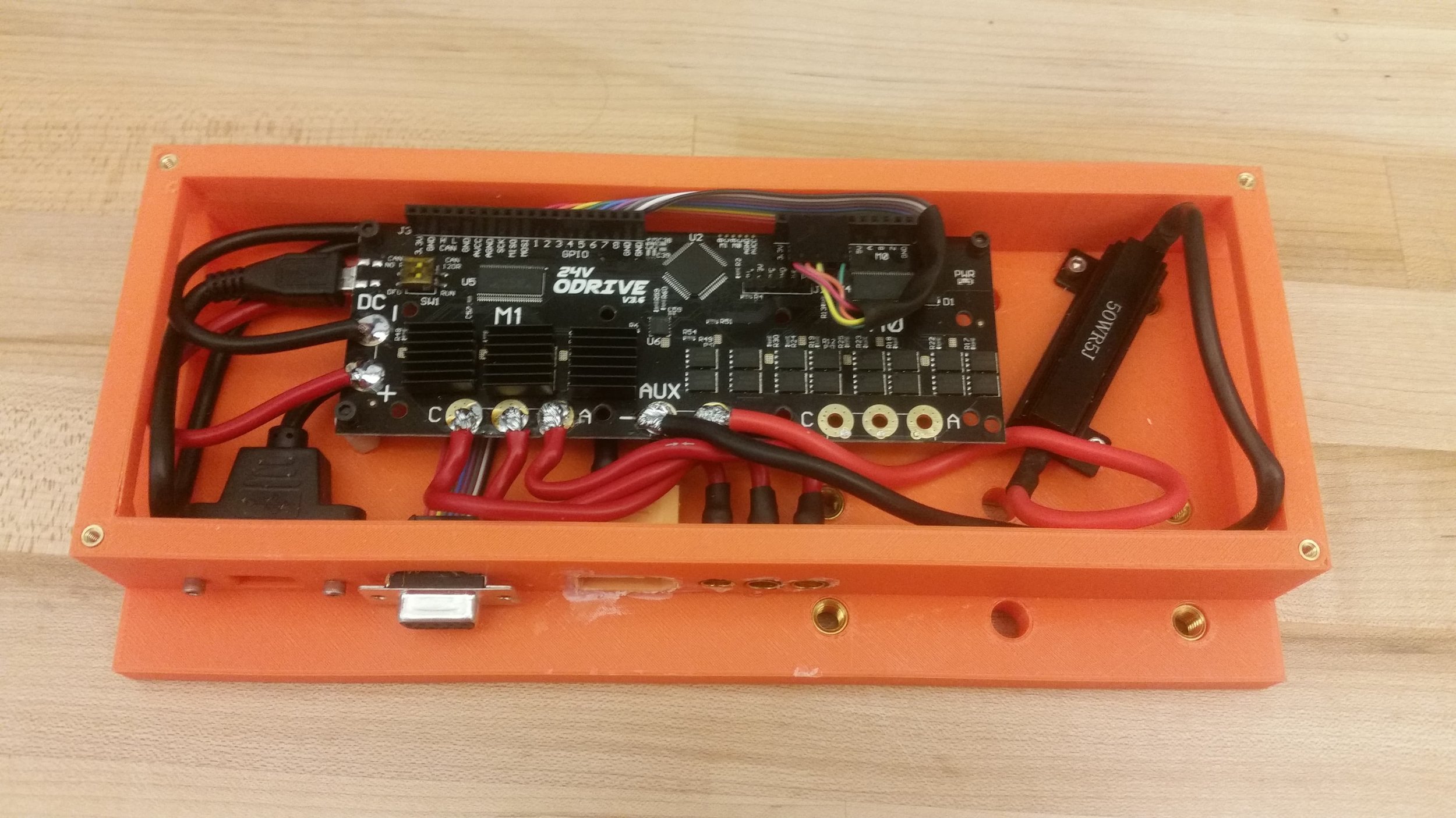
The ODrive housing, is mounted on the underside of the flying bridge, and holds the Odrive and its attendant power resistor. This housing was developed in it’s current form for our tests at Eagle Mine, and is intended to be dust and splash resistant, and features panel mount connectors for everything except the auxiliary power output (which is run out the air vent if needed).

With both fans running, we found the maximum sustainable current to be somewhere on the order of 70amps. During autonomy testing we were able to set our current limit to 85a peak, with an ambient temperature of 105f and experienced no issues while testing.

ODrive:

Review:

The ODrive is a two-channel brushless servo controller, with built in FOC. The peak current is around 100a and the sustained current capacity is on the order of 70, depending on cooling. The unit comes in either a 24v, or a 56v configuration, and can communicate over serial, USB, CAN, or PPM. Although it should be noted that USB is the only option that is fully fleshed out. The price at time of writing is around 120$ for the low voltage variant, and 150$ for the high voltage variant.

In practice, we found that the ODrive worked okay, but had lots of fairly fiddly configuration that needed to be worked out. Not all of which was documented on the Odrive website. I would certainly re-use the ODrive for a budget-constrained vehicle project in the future, and would have no qualms about using it as a position controller (which is what it is really designed for), but would be hesitant to install it in a high-reliability application where the occasional re-start is unacceptable. The learning curve is fairly steep if you have no prior experience with FOC or servo controllers, so expect to allocate around 2 weeks to getting comfortable and then around 1 week to actual setup and testing.

Integration:

The original encoder setup. The new one keeps a similar structure, but switches to an in-line no contact magnetic encoder. With this configuration we periodically lost ticks and would eventually see the FOC fail when it lost track of the rotor posit…

The original encoder setup. The new one keeps a similar structure, but switches to an in-line no contact magnetic encoder. With this configuration we periodically lost ticks and would eventually see the FOC fail when it lost track of the rotor position.

Once connectorized, the ODrive had no issues with driving Balto’s main drive motor. We used an AS5047p magnetic encoder, mounted in-line with the motor, with the magnet directly mounted to the motor shaft, to provide ABI feedback. We did find that the index pulse is a non-optional part of the setup, as it allows ODrive to prevent the accumulation of missed encoder pulses (which did occur). The encoder is mounted to a vertical plate, which is in turn mounted to a small 3D printed breadboard that exactly fits into the chassis, and is then glued in place. For competition, we have short motor and encoder cables, but have not had any problem using longer cables (order of 2 feet) during testing. It should noted that although the system is wired for SPI communication, that is not currently supported by the ODrive, so only relative position is used.

Configuration Settings:

By far the most important part of using an ODrive (as with any motor controller really) is getting it configured correctly. Rather than storing our configuration settings on the motor driver, we choose to re-upload our non-standard configuration settings each time the Odrive is reset. This worked well, and helps us keep our ODrives interchangeable for other projects as needed. We also fully redo the calibration process each time the ODrive is initiated. This introduces terrain dependent variability though, so I would be cautious about taking the same approach.

We still have a few issues with our performance, and of course our settings are specific to the motor and power train we were using, but on the whole they did work well so I have included them below for reference. Note that if your hardware is different you will need different values.

  • axis1.motor.config.current_lim = 80

  • axis1.controller.config.vel_limit = 233333 + 50000

  • axis1.motor.config.calibration_current = 40

  • config.brake_resistance = 0.8

  • axis1.motor.config.pole_pairs = 2

  • axis1.encoder.config.cpr = 400

  • axis1.motor.config.requested_current_range = 60

  • axis1.controller.config.control_mode = 2

  • axis1.encoder.config.use_index = True

  • axis1.controller.config.vel_limit_tolerance = 0

Splash Proofing:

The housing fully assembled in it’s “splash proof” configuration. The lack of sealing around the edges is a little worrying, but did not prove an issue in practice. For future builds laser cut gaskets could be used.

The housing fully assembled in it’s “splash proof” configuration. The lack of sealing around the edges is a little worrying, but did not prove an issue in practice. For future builds laser cut gaskets could be used.

One of the key requirements for this motor housing was that it be as splash proof as possible. This was accomplished by adding a cover plate to the air inlets, and a circuitous path to the air outlet. As designed, there is no way for water to directly splash onto the PCB without taking at least two 90 degree turns. The panel mount connectors were sealed with CA glue (if permanent) or glue-gun glue (if temporary). During testing at the Eagle Mine, we created puddles and ran Balto through them without any issues. The system also held up fine at the actual competition which featured puddles on the order of a few inches deep. Although not as secure as full waterproofing, I do like this design and plan to re-use it for other protects.

Build Log:

Before beginning the build, it is important to source all of the required parts. This means printing the base and flue, along with the upper and lower Odrive covers. We choose to laser cut the covers for aesthetic reasons, but all parts can be printed on a Craftbot+ if need be. A soldering iron, Locktite 222, CA glue, heat shrink, 14 gauge wire, ribbon cable, and pliers will also come in handy. All of the mechanical hardware can be purchased from Micmaster, and the electrical hardware (excepting the Odrive itself) can be purchased from Digikey. Please see the list below for an approximate list of the require parts. The various wires, cables, and pin headers are also required along with lock washers or Locktite.

Purchased Components:

Most of the required parts laid out prior to assembly

Most of the required parts laid out prior to assembly

  • (12x) 1/2in 4-40 standoffs.

  • (10x) 4-40 x 1/4 cap screws.

  • (8x) 4-40 x 3/8 cap screws.

  • (8x) 1/4-20 heatset inserts.

  • (22x) 4-40 heatset inserts.

  • (2x) 40mm 12v fan.

  • (2x) male XT60

  • (1x) female XT60

  • (1x) female XT90

  • (3x) 6mm female bullet

  • (1x) Odrive, no headers.

  • (1x) D-SUB, 9 pin, female —> ribbon.

Assembly Steps:

68966651_726986087749181_3651018592998129664_n.jpg
69069669_2362534380654852_2825536581765431296_n.jpg
  1. Insert the heat-set inserts into the 3D printed and laser cut parts. Note that the outer four holes, and middle two holes on the lower lid are clearance holes. Likewise, the four holes on the upper lid are all clearance holes and do not need heat-set inserts. For the 1/4-20 heat-set inserts, only the four outer holes in each six hole pattern are used. The middle two can be left empty.

  2. Install the Odrive, Odrive resistor, fans, and upper and lower lid plates. Once the heat-set insert angles have been confirmed as adequate, remove the two lid plates, leaving the Odrive board and Odrive resistor installed.

  3. Solder together XT90 input cable, resistor lines, and female 6mm bullet connector cables, using the housing and installed Odrive to get the correct lengths. Take care to leave several inches of extra length for connecting each wire to the Odrive. All of these connections should be made with high current (14 gauge or larger) wire. Heat shrink should be used to insulate all connections, and should extend fully over the bullet connectors.

  4. Next assemble the female D-SUB panel mount connector. If using multi-colored wire place the black strand such that it runs to the first position on the connector. Measure the ribbon cable to the 1st encoder input on the Odrive and cut it with about 1.5 inches of margin. Once cut to length, connect the 5 position crimp-on connector with male pins using the following mapping. The D-SUB pin numbering follows the standard convention for this project.

    1. 1st D-SUB (MISO) —> NC.

    2. 2nd D-SUB (GND) —> 5th crimp position.

    3. 3rd D-SUB (MOSI) —> NC.

    4. 4th D-SUB (B) —> 3rd crimp position.

    5. 5th D-SUB (CLK) —> NC.

    6. 6th D-SUB (A) —> 2nd crimp position.

    7. 7th D-SUB (CS) —> NC.

    8. 8th D-SUB (5v) —> 1st crimp position.

    9. 9th D-SUB(INDEX) —> 4th crimp position.

  5. Test fit all panel mount connectors, including the usb panel mount, and check all of the required lengths. If viable solder the wires in place as appropriate and use CA glue to secure the XT90 connector, and bullet connectors in place. Otherwise, revise any incorrect lengths. The USB mount, and D-SUB can be secured with screws, (though the D-SUB should snap in place).

  6. Using medium (larger than 19 gauge) wire, solder the two auxiliary power taps onto the Odrive itself. One should extend into the housing for use powering the fans, and the other should extend out of the housing through the air vent for use powering the steering system if needed.

  7. At this point the housing should be fully assembled in an electrical sense. It may make sense to test that it works now, before progressing on to the cooling fans and lids.

  8. Thread the fan wires through the small holes in the larger of the two lid plates. Be sure to include some heat-shrink or other tubing to provide strain and abrasion relief. The fan wires can now be soldered together to an XT60 connector.

  9. The entire housing can now be assembled. Use ether lock washers, or low strength Locktite to secure all of the screws, and be sure to thread the external power tap out through the vent if in use.

Stepper Motor Driver

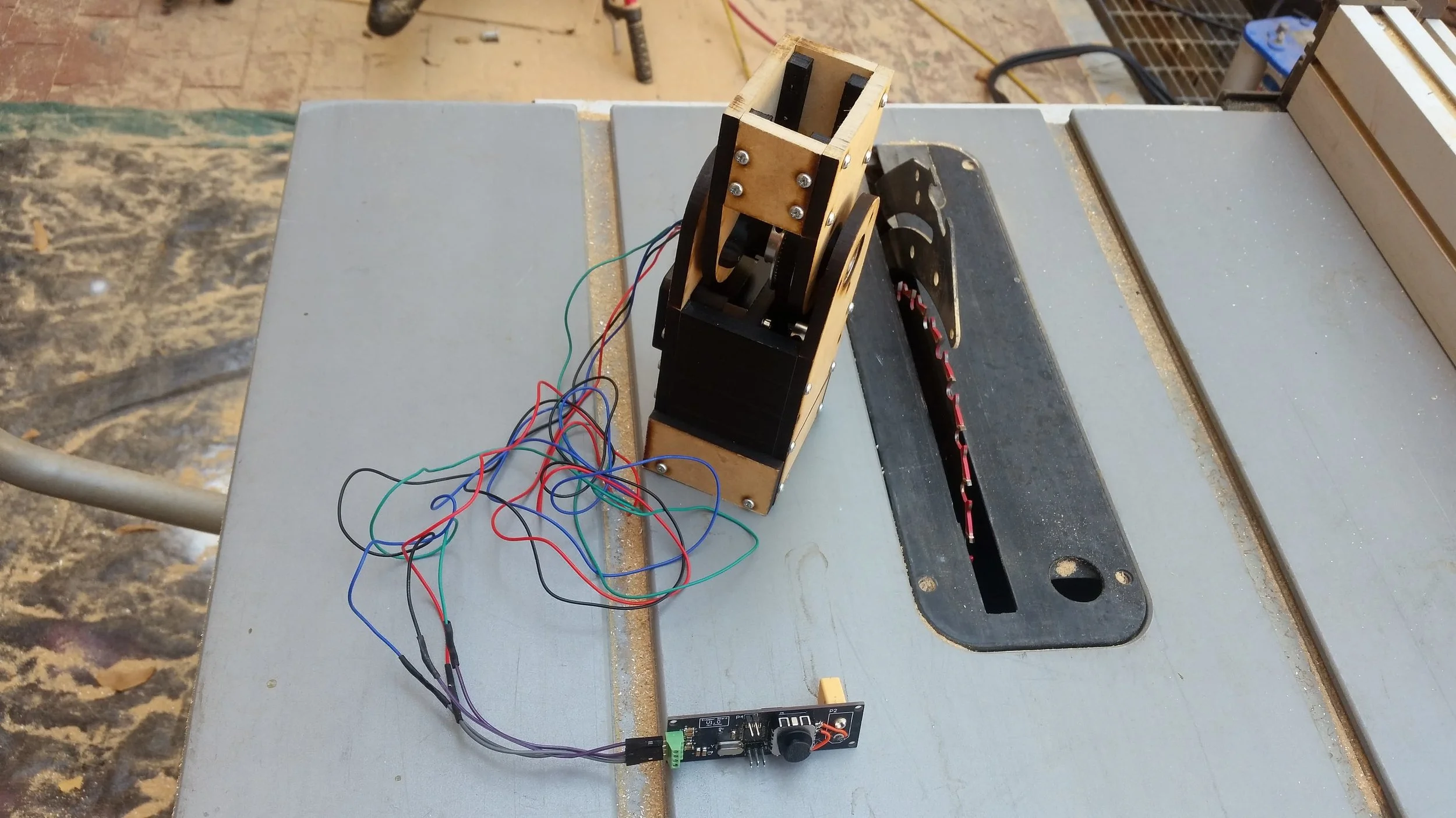
Version 1.0 of the controller. I did need to make one minor rework on the joystick inputs, but other than that it worked perfectly. The green header connects to the motor, the 6 pin header is for programming, the 2 pin header is for debug, and the o…

Version 1.0 of the controller. I did need to make one minor rework on the joystick inputs, but other than that it worked perfectly. The green header connects to the motor, the 6 pin header is for programming, the 2 pin header is for debug, and the orange XT60 connector on the back provides power. (These pictures were taken before cleaning the flux)

Summary:

This is a generic stepper driver motor tester that should work with a range of NEMA 11, and NEMA 17 motors. Moving the joystick forward and backward allows for a range of step rates in both directions, and flicking the joystick right or left allows the user to select from between 1/2 and 1/32 microstepping. The MCU is an 328p flashed with an Arduino Nano bootloader, and the stepper driver is a DRV8825.

This was a pretty simple project, so I have elected not to include a build log. The gerber files, Altium project, and arduino files can be found below along with instructions for adding your own logo, and my suggested improvements for the second revision.

Improvements:

I don’t expect to make a second rev of this project any time soon, but if I did I would suggest the following modifications:

  • Consider switching to a Trinamic or generally better quality driver.

  • Run the driver feedback lines to LEDs rather than IO pins.

  • Provide user-accessible current configurations.

  • Snap-lock connectors would be better for the stepper wires.

Logo:

This is my first PCB to bear my makers mark! Adding a makers mark to my PCBs has been a goal for a while, but I haven’t been able to justify the time on previous boards. Turns out the process is pretty simple:

  • Get a DXF of the logo. I explored from the wax stamp CAD, but there are lots of ways to do this.

    • (Optional) Clean up the file in Inkscape to get exactly what you want. It’s easier to edit here than it will be in Altium.

  • Using “File -> Import -> DXF/DWG” enter the import wizard. I used the following settings with some success:

    • 1 AutoCAD unit: 200mil

    • Default Line Width: .1mm

    • Layer_1 : Top Overlay (this is likely specific to my file / Inkscape)

Crawler E-stop

The e-stop installed on Balto, with our test transponder in palace of DARPA's.

The e-stop installed on Balto, with our test transponder in palace of DARPA's.

Overview:

One of the key requirements for any large (we count) robot competing in the DARPA challenge is a functioning estop system. When our original solution couldn’t be delivered on time, we decided to build our own. This is one of the rougher systems on the robot, mostly because it was built in so little time, but it works well, and is definitely nice to have. I plan to use a similar architecture (dropping Tier 2) on future robots even when it is not required.

Requirements:

For SUBT, DARPA requires that teams implement a 3-tiered E-stop system as follows. They also require that the robot give some indication that it is in an e-stopped state for tier 2 triggers. DARPA does not require that teams implement hardware E-Stops. However, for tier 3 that does seem prudent.

  • Tier 1: A wireless E-Stop controlled from the team’s base station.

  • Tier 2: A wireless E-Stop controlled by an XBee transponder mounted to the robot and controlled by DARPA.

  • Tier 3: A physical latching E-Stop (big red button).

For the first and second tiers, we will use a piece of code that inserts zero-motion commands to the twist mux node at a higher priority than ether the joystick or move-base. A Teensy (running similar firmware to steering) will be used to monitor the transponder for shutdown requests.

The system block diagram for Balto’s e-stop. The pullups are nice to have, but can mostly be ignored.

The system block diagram for Balto’s e-stop. The pullups are nice to have, but can mostly be ignored.

Balto with a tier 2 e-stop enabled. Note the Blue indicator led is lid.

Balto with a tier 2 e-stop enabled. Note the Blue indicator led is lid.

documentation:

(versions as of 8/5/2019)

Assembly:

This part of the project was completed on a very short time scale after our original solution fell through. It is a pretty rough build, and so I have left these notes pretty bare bones on the theory that (hopefully) I will be the only person needing to follow them. If that is not the case, and you are confused definitely feel free to reach out and I’d be more than happy to walk you through the process.

One item of particular note is the pin numbers. I frequently refer to pins according to a numbering scheme which is specific to the crawler project. It runs as follows: For all D-SUB connectors, pins are numbered such that looking at a female connector, with the short side facing up the first pin is in the lower left corner, and the second pin is in the upper left corner. For through-hole headers, the pins are numbered such that with the shroud gap facing down pin 1 is in the lower left hand corner of the header, and pin 2 is in the upper left hand corner of the header. I picked this numbering scheme because it means that adjacent wires in a ribbon cable increase and decrease by 1 relative to their neighbors. By convention, I have oriented the ribbon cable such that black is always pin 1 and red is always pin 9, the 10th pin on the rectangular headers is never used.

The CADs, firmware, and control software can all be found on the github. In addition to the 3d printed parts, the following components were used (along with ribbon cable and heavier gauge wire for power transmission.

Perf Board:

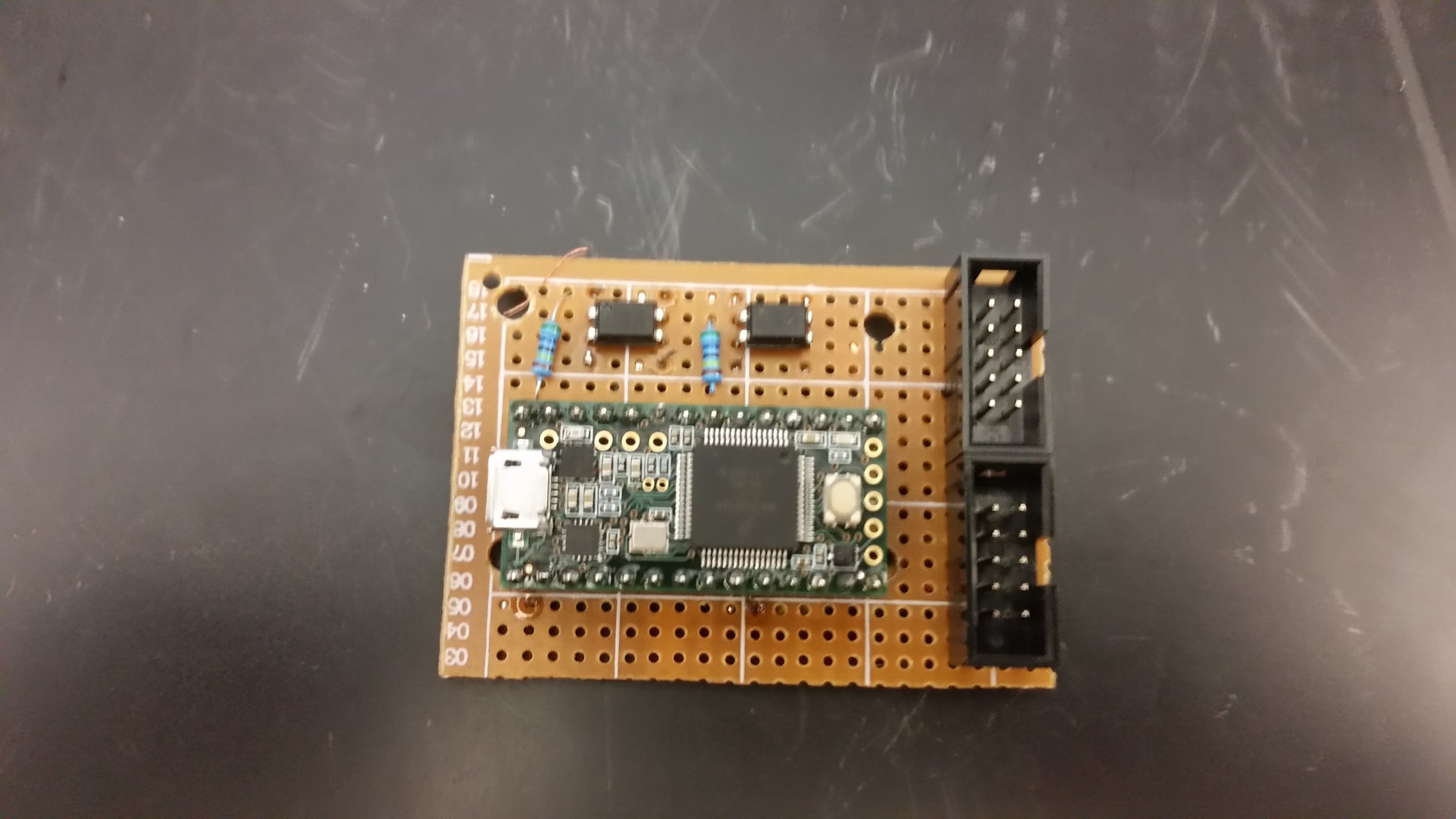
The first step in building the e-stop is to build up the perfboard with the Teensy and two optocouplers. The perfboard is by far the most fiddly part of the build, and I plan to replace it with a PCB when time exists. In the mean time, I have included fabircation suggestions and wiring notes below.

Begin by drilling and cutting a piece of perfboard to match the schematic in figure A. Once that is done, solder the Teensy headers (or Teensy itself, though I would advise against it), optocouplers, and shrouded headers, roughly as shown in figure C. Next, both optocoupler’s input cathode’s to Teensy ground, and the input anode’s to D16 and D23 (for led control and main power control respectively). Now, verify that the connections work by writing a test script to the Teensy (really, you want to catch these issues now before the rest of the wires go on), then connect the two shrouded headers according to the following tables.

Header 2:

This header connects the teensy to the D-Sub panel mount connector by way of a ribbon cable.

Pin 1 - Optocoupler High Side (D23 controlled)

Pin 2 - Optocoupler low side (D23 controlled)

Pin 3 - Optocoupler high side (D16 controlled)

Pin 4 - Optocoupler low side (D16 controlled)

Pin 5 - Short to pins 6 and 8

Pin 6 - Short to pins 5 and 8

Pin 7 - Short to pin 3

Pin 8 -Short to pins 6 and 5

Header 1:

This header connects the teensy to the D-Sub panel mount connector by way of a ribbon cable.

Pin 1 - Teensy Ground

Pin 2 - Teensy 5v

Pin 3 - Teensy D8

Pin 7 - Teensy D10

Pin 8 - Teensy D9

Figure A: Cut down the perf board to match these dimensions and holes. When in doubt it is better to be slightly too small than too large, as you won’t be lacking for board space.

Figure A: Cut down the perf board to match these dimensions and holes. When in doubt it is better to be slightly too small than too large, as you won’t be lacking for board space.

Figure C: The pulldown resistors in this photo are optional, and I would suggest leaving them off.

Figure C: The pulldown resistors in this photo are optional, and I would suggest leaving them off.

Figure B: The underside of the board, presented here with some horror. Note that the high-side input for the main power optocoupler is provided by a resistor. (In my defense, we were very short on time and I did clean it up more before install)

Figure B: The underside of the board, presented here with some horror. Note that the high-side input for the main power optocoupler is provided by a resistor. (In my defense, we were very short on time and I did clean it up more before install)

Figure D: Place the reference corner of the board in the forward/top corner of the housing wall.

Figure D: Place the reference corner of the board in the forward/top corner of the housing wall.

Wiring:

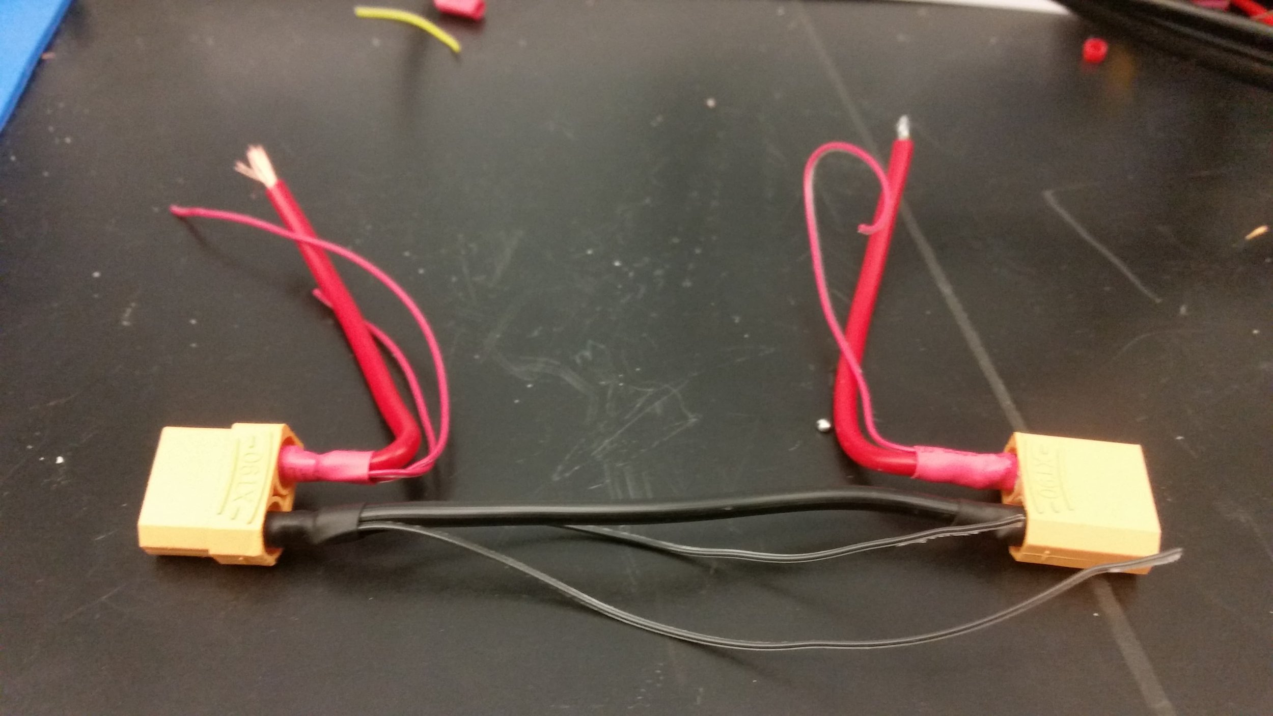
Figure E: Power wiring harness, the ground wire should be sized to fit across the estop housing. The vcc wires should start out around 6in in length and can be cut down to ease assembly once the other wiring is completed.

Figure E: Power wiring harness, the ground wire should be sized to fit across the estop housing. The vcc wires should start out around 6in in length and can be cut down to ease assembly once the other wiring is completed.

Once the perfboard is completed, begin the wiring process. First, create the power wiring harness as shown in Figure E (Note that it is easier to make the VCC wires shorter than longer), and test that it fits across the housing. You will want to use no less than 14 gauge wiring, and 12 would be better if available. Note the secondary wires, which will be used to run power to the switching system and indicator led.

With the power harness completed, the next step is to begin routing each component. The list below outlines how each component is connected to the others. Unless otherwise noted, all connections can be made with 26 gauge wire. For connections running to crimp terminals use solder balls or crimp-on ring terminals. For connections running to the perf board use single location femail pin headers.

All of the components connect to the second pin header except the ribbon cable.

Connections by component:

Estop switch block - One terminal connects to VCC IN, the other connects to the perf board (pin 2).

Estop led block - One terminal connects to perfboard pin 7, the other connects to perfboard pin 8.

Indicator led - One pin connects to perfboard pin 4, the other connects to perfboard pin 8.

VCC IN - Connects to the SSR high side (12 gauge wire), Estop switch block.

VCC OUT - Connects to the SSR low side (12 gauge wire), perfboard pin 3.

SSR - Switch H: pin 1, Switch L: battery ground, Controlled H: VCC IN, Controlled L: VCC OUT.

A not-quite-final test fitup of the wiring. I strongly recommend making the leads as long as possible even if it makes assembly slightly trickier.

A not-quite-final test fitup of the wiring. I strongly recommend making the leads as long as possible even if it makes assembly slightly trickier.

Connections by pin (header 2):

Pin 1 - SSR control high side.

Pin 2 - Estop switch terminal block.

Pin 3 - VCC OUT (XT90 output).

Pin 4 - Indicator led(either lead).

Pin 5 - Battery GND.

Pin 6 - Indicator led(either lead).

Pin 7 - Estop led terminal block (either terminal).

Pin 8 - Estop led terminal block (either terminal).

The panel mount connector should be outfitted with a ribbon cable long enough to reach the perfboard, connected such that pin 1 on header 1 connects to pin 1 of the D-Sub connector. With the wiring complete you can now install the SSR onto the bottom plate, and the E-stop, indicator led, perf board, and panel mount connectors into the housing.

Transponder:

After you have assembled the e-stop housing, and tested that all of the components work, the final step is to wire up the transponder carrier board. Connect a male D-Sub connector to a length of ribbon cable, and then solder the ribbon cable in place according to the following table. Note that pins are given according to their female counterpart (and incidentally their corresponding perfboard pin). Once you have installed the transponder and verified that it works, consider using epoxy or CA glue to strain-relieve the solder joints.

Pin 1 - GND

Pin 2 - 5V

Pin 3 - DIO1

Pin 7 - DIN

Pin 8 - DOUT

Crawler Steering

Page Overview:

The completed inside of the steering module. I don’t love the force being exerted on the usb connector, but at least this way there’s minimal cycling.

The completed inside of the steering module. I don’t love the force being exerted on the usb connector, but at least this way there’s minimal cycling.

This page documents the assembly process for version 1.2 of the Crawler’s steering module. This version is backwards compatible with V1.1, but now features panel mount IO ports to bring it in-line with the current generation of the O-Drive housing. We are considering this steering module to be “mud resistant” but it is in no way waterproof.

Note: For now I am not going to be posting code, or cads, for this project. With that said, if you are looking to make something similar please do message me and we can work something out (there’s a contact form on the “about” page).

Project Overview:

This post is part of my ongoing efforts to develop a new ground robot for Caltech’s/JPL’s DARPA challenge team. This year’s competition is to create a team of robots to explore an underground environment and report back a map, along with the location of specific objects inside the cave network.

Competition web-page: https://www.subtchallenge.com/

My specific project is to convert a Traxxas X-MAXX to be fully autonomous. It is hoped that the X-MAXX platform will be both faster, and more versatile, than the husky we use now (not to mention cheaper).

Build Process:

Notable Parts:

  • 4-40 heat set inserts (8)

  • 4-40x3/8 socket head cap screws (8)

  • Female nine pin D-Sub, panel mount, PN: A-DFF 09LPIII/Z

  • Female 10 pin ribbon cable header, PN: 61201023021

  • Male 10 pin header with shroud, PN: 61201021621

  • nine strand ribbon cable.

  • usb panel mount from Adafruit.

Assembly Steps:

  1. Print the housing, lid, and drill jig. It is recommended that the wall and top/bottom thickness exceed 1.6mm. Infill should be set at greater than 15%.

  2. Cut the proto-board to:

  3. Place the proto-board beneath the drill jig. Use the jig to drill the 4 mounting holes, then cut the proto-board to size (being sure to leave at least 4 full rows to each side of the Teensy).

  4. Install the heat-set inserts in the housing using a soldering iron.

  5. Solder the pin-header in place with the notch facing the Teensy and then solder each pin as follows:

    1. NC

    2. NC

    3. Connect to pin 6.

    4. Connect to Teensy ground.

    5. Connect to Teensy ground.

    6. Connect to pin 3.

    7. Connect to Teensy pin D5.

    8. NC

    9. NC

  6. Assemble the D-Sub cable such that pin one of the D-Sub and pin one of the female pin header are connected. The pin header has a small triangle to mark pin one.

  7. Install the D-Sub connector and panel mount usb. Coil and secure the USB cable as needed.

  8. Test and Install!

V1.1 for comparison.

V1.1 for comparison.

V1.2 of the steering module installed on our first robot.

V1.2 of the steering module installed on our first robot.

Chassis Side:

In the robot chassis place a BEC (connected to the ODrive auxiliary power tap) and distribution board connected as follows.

The wiring from the 6 pin header to the two 3 pin headers.

The wiring from the 6 pin header to the two 3 pin headers.

I would strongly encourage closing the lid prior to testing…

I would strongly encourage closing the lid prior to testing…

Belt Grinder: Structure Build

Summary:

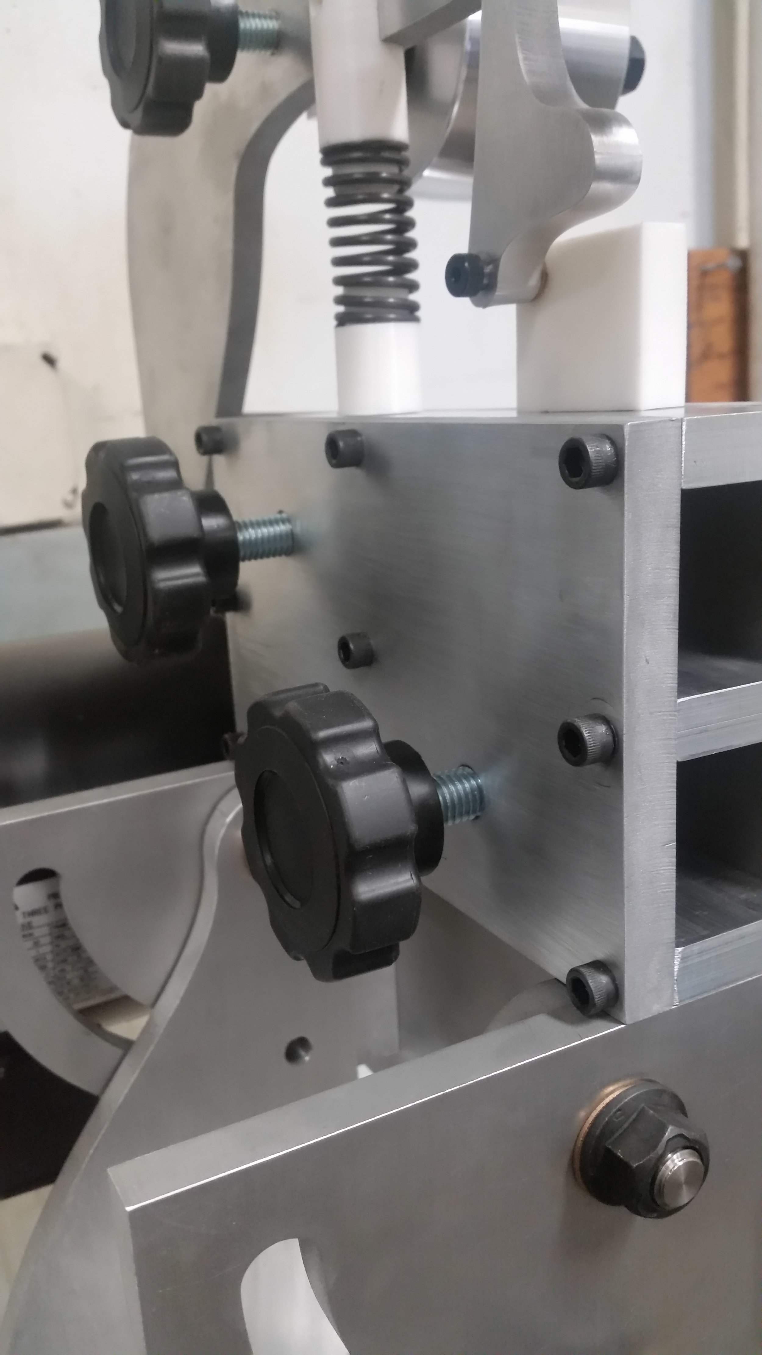
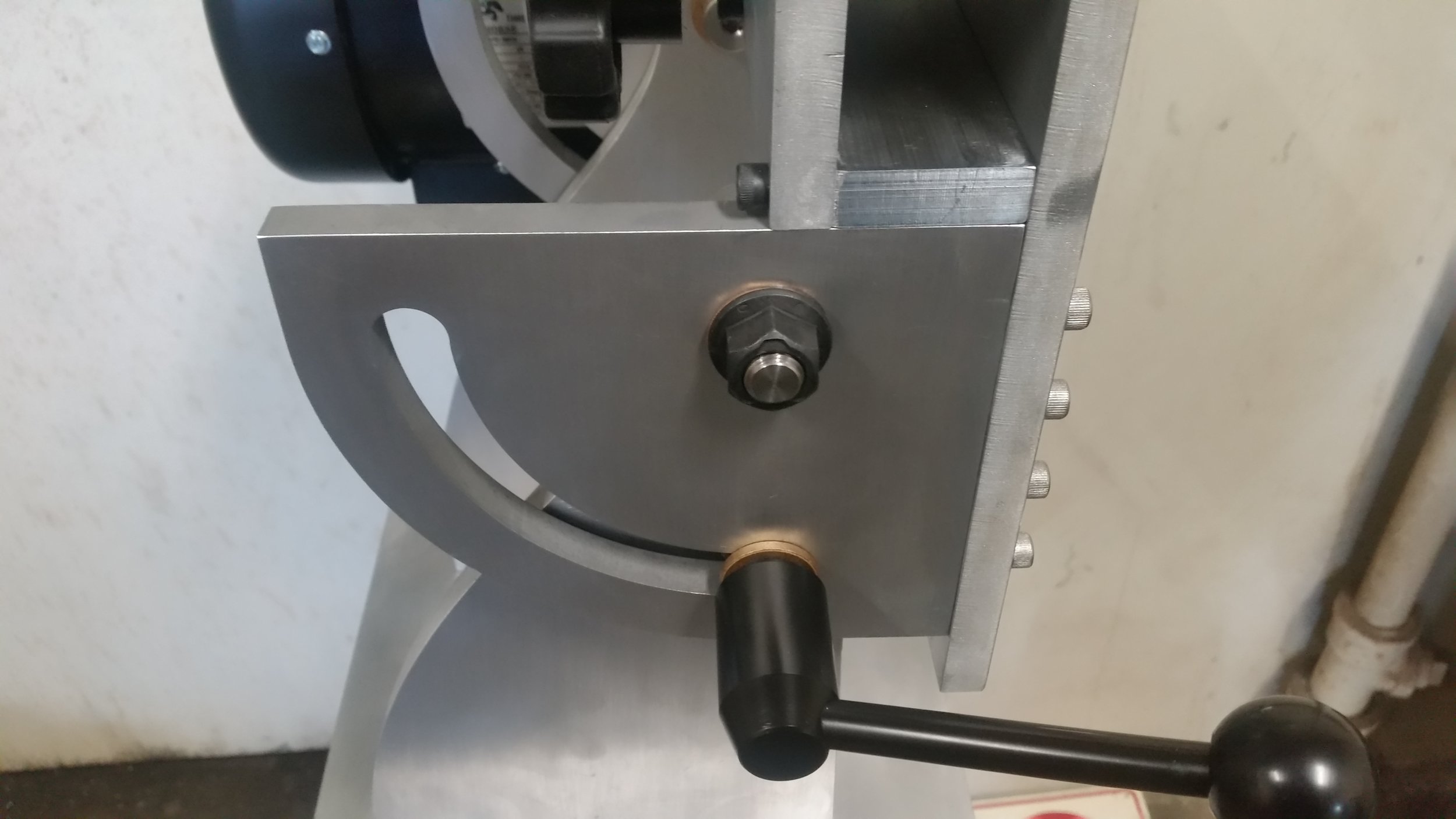
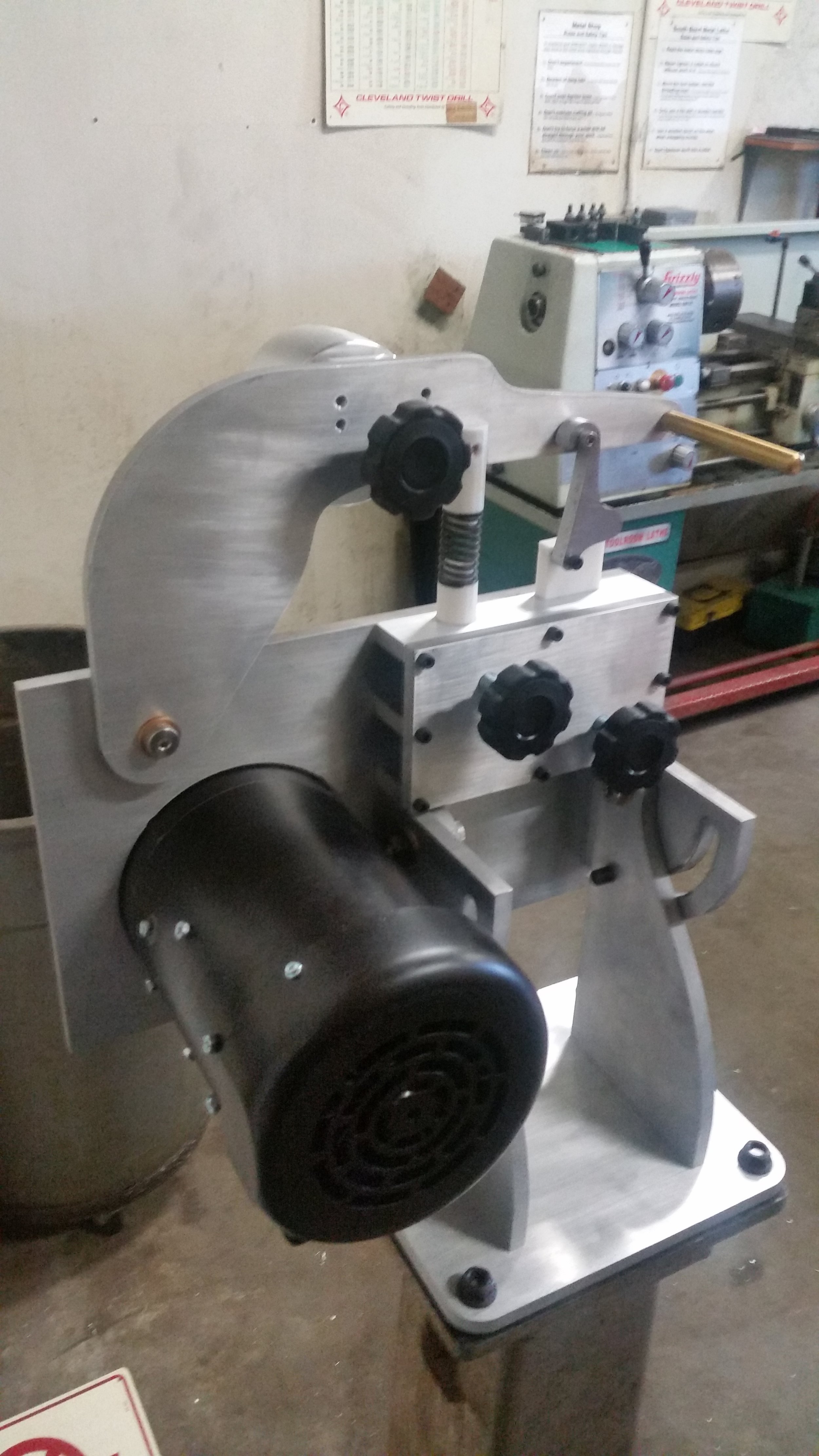
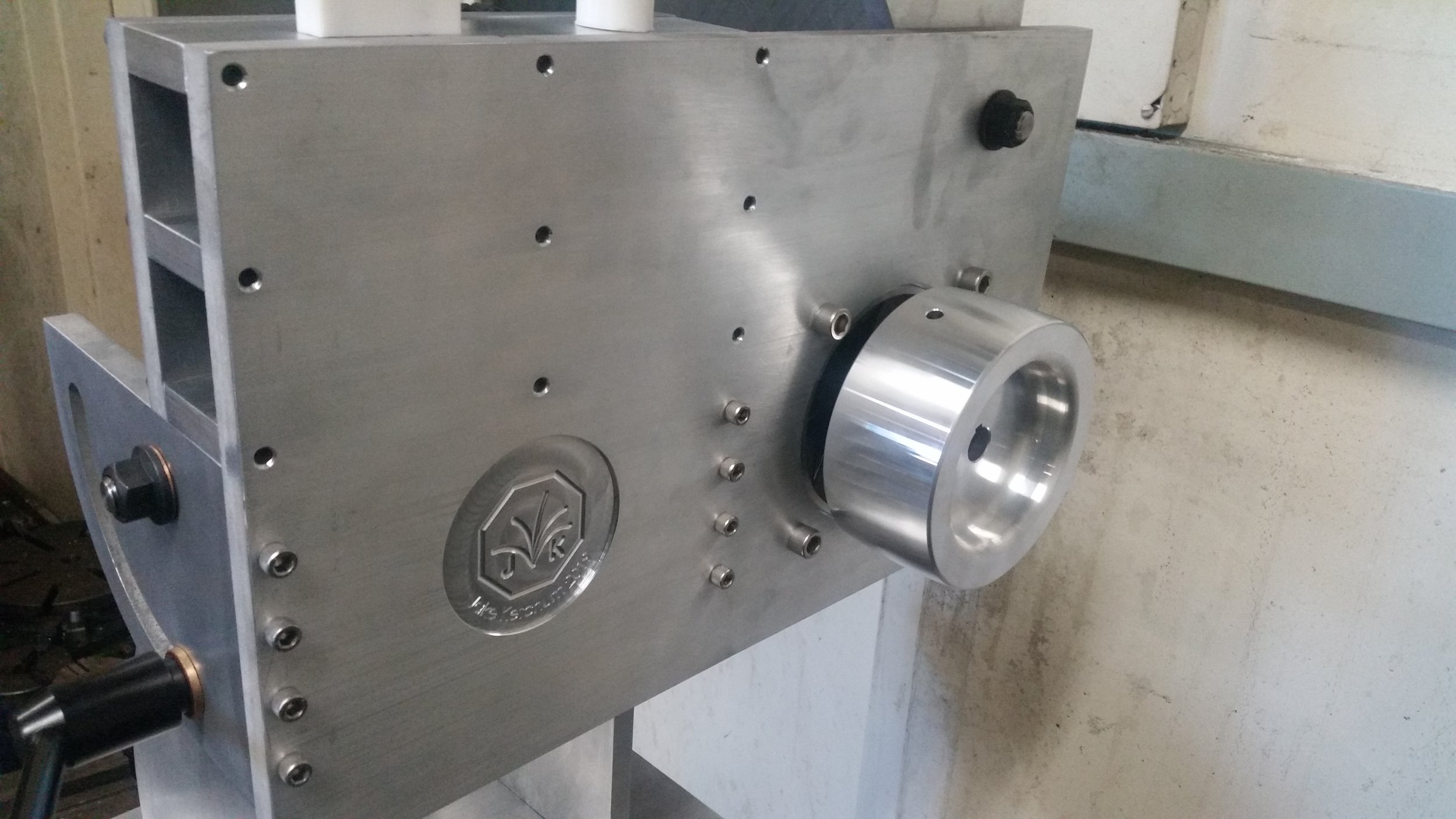
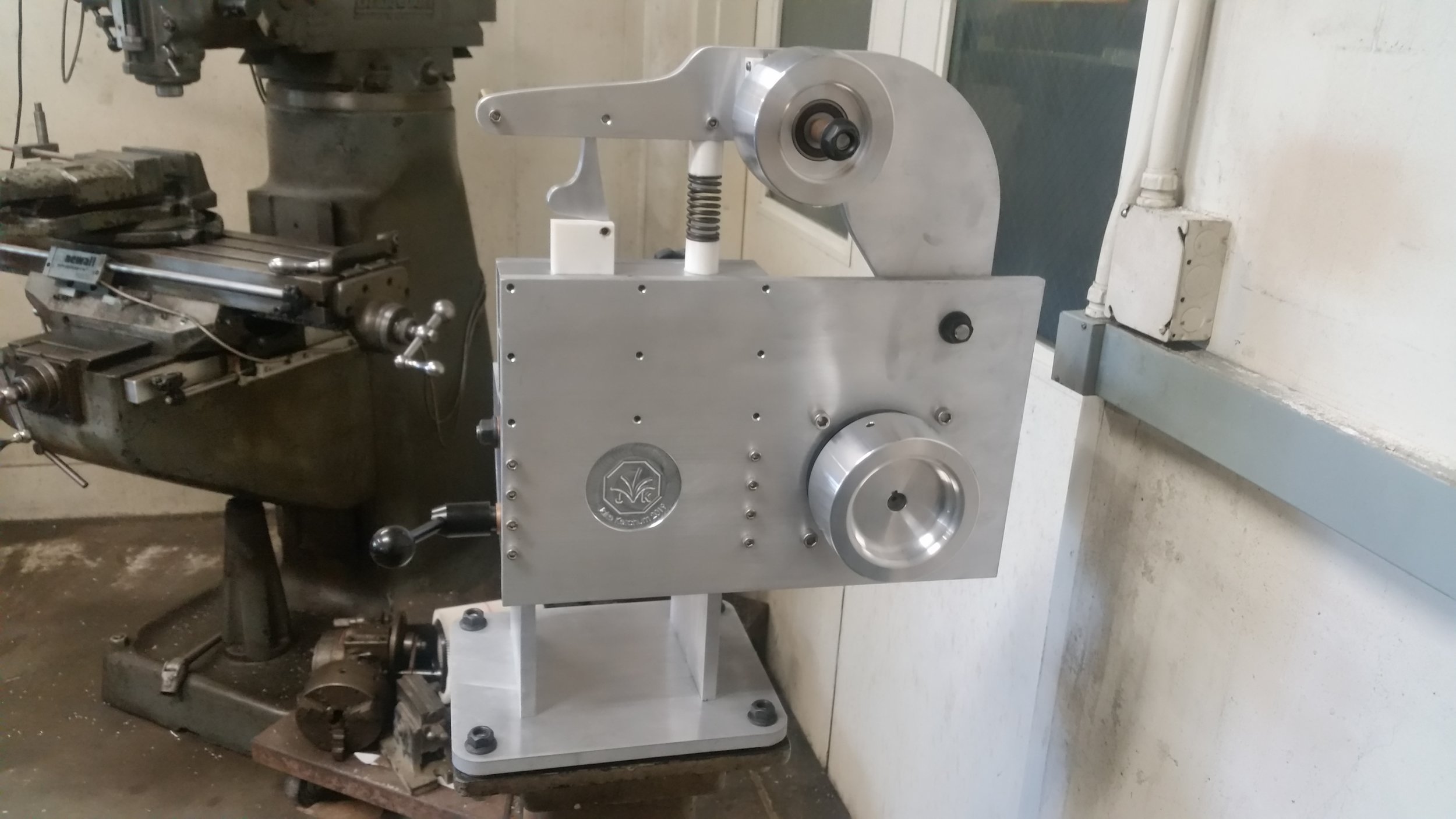
Greetings! This is my build log for the main body of the belt grinder. During this phase of the process, my goal is to complete fabrication of the main structural plates, and then to assemble a mockup of the grinder body. This will let me get a sense for the machine’s ergonomics before setting up the electronics and finalizing the platen design. At this point the grinder is installed and the pivots all work. Next up will be fabricating the platen assembly, and installing the electronics. Until the grinder is up and running we won’t really know how it works, but for now I am very pleased. All of the moving parts turn smoothly, with minimal slop, and the overall structure seems solid. The hold-down lever in particular works quite well (credit to Reeder Grinders for that idea).

I have organized this build log (and pictures) by machine used, rather than part created, since that best matches my actual process for this project. It is also worth noting that both the handle, and tracking plate are completed in these pictures. However, I’ll include their build logs later.

Assembly:

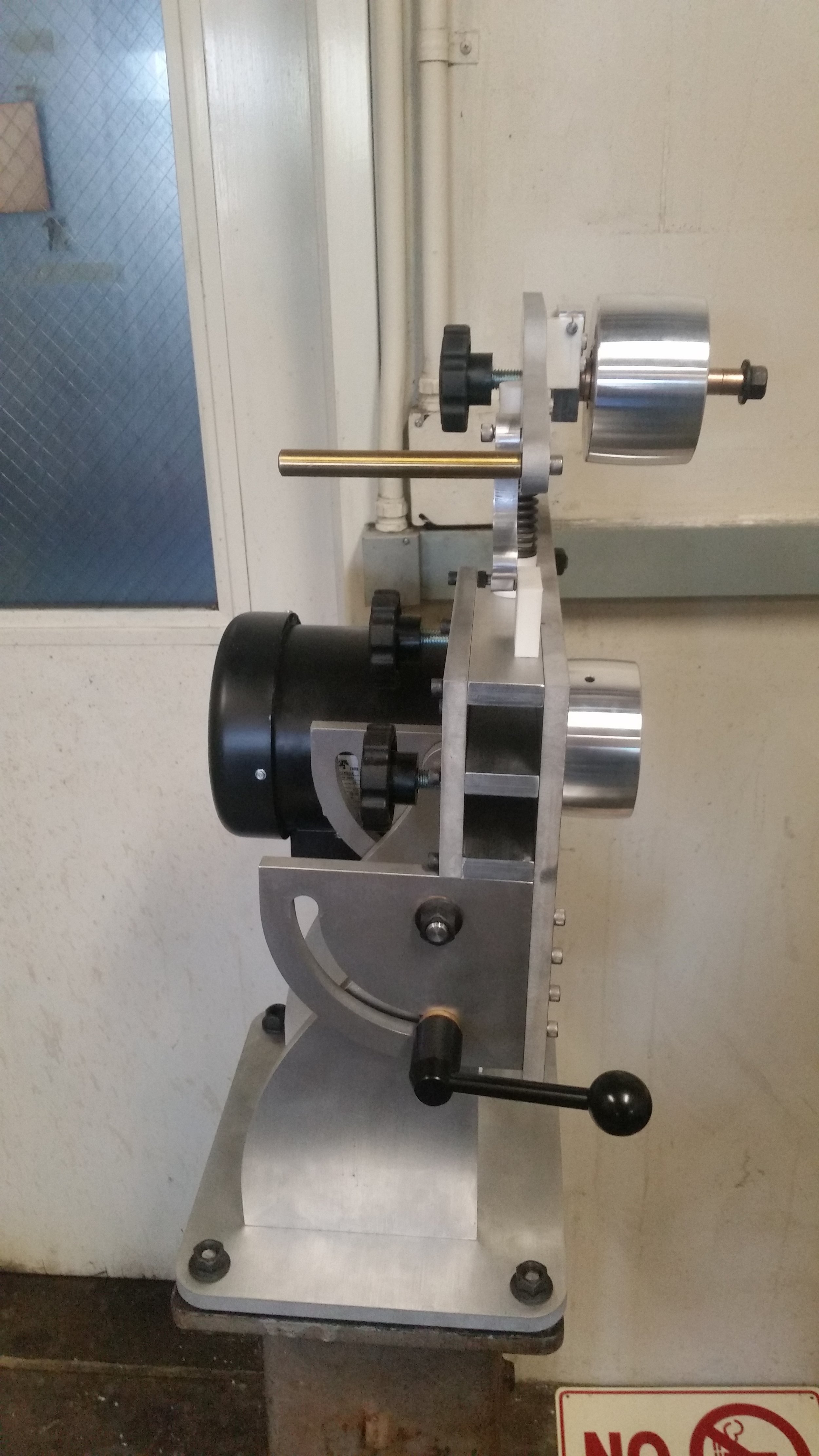
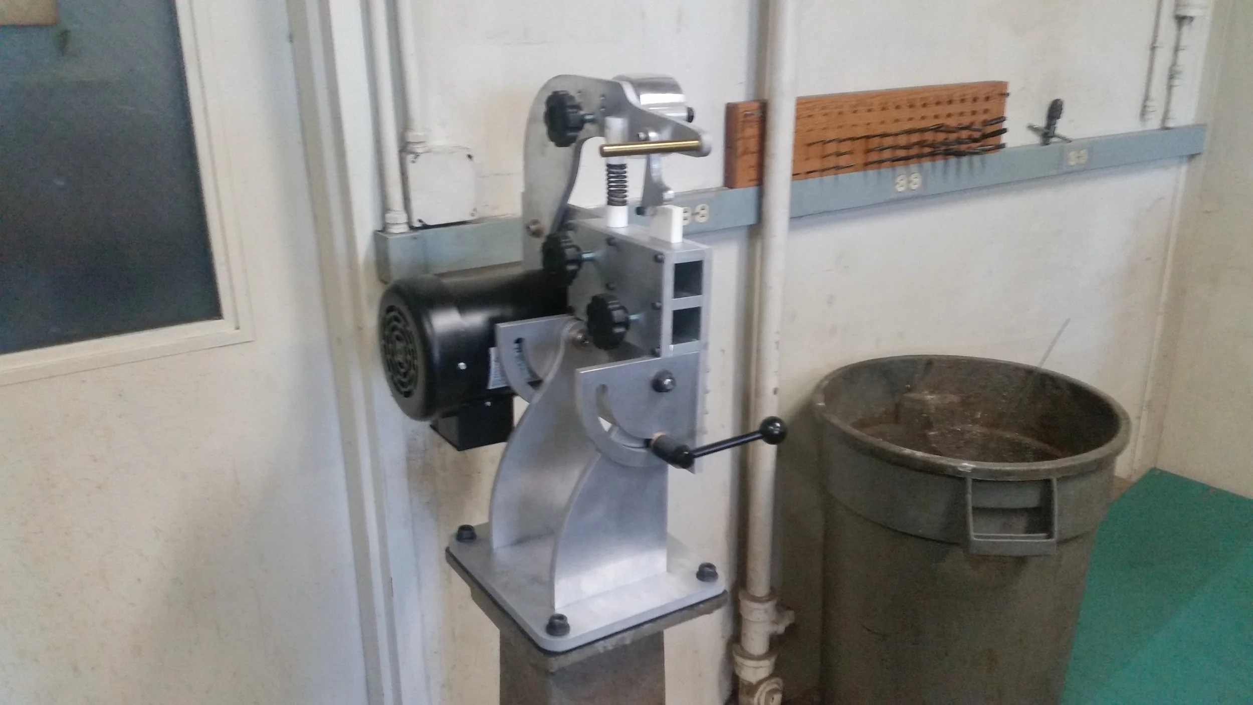
The grinder, fully installed in its temporary home. At this point the structure, and most of the mechanisms are together. Though the tracking adjustment and spring tension will need to be tuned in after the platen build is complete.

The grinder, fully installed in its temporary home. At this point the structure, and most of the mechanisms are together. Though the tracking adjustment and spring tension will need to be tuned in after the platen build is complete.

All things being equal, the assembly process was remarkably painless. All told the assembly took about 3 hours and, for me, really validates this type of waterjet + drill press construction as a way of building/prototyping large structures. I have included a summary of my process below for anyone looking to build a similar grinder (and for my own reference).

  • I started out by using 220 grit sandpaper to give the parts a decorative “brushed” finish. This largely produced the aesthetic I was going for, though on some parts I did have to step down to 80 grit to remove some burrs and nicks. I then washed all the pieces with soap and water, after using IPA to remove the leftover sharpy and marking dye.

  • I then clamped the base plate in place above the pedestal ( a lovely Stanley grinder stand we have left over from a dead grinder) and used a hand drill to drill mounting holes in the base, with the corresponding base plate holes as a guide. This worked well, but probably should have been done before the cosmetic touch-ups.

  • I then separately assembled the pivot arm, back-plate with pivot plates, and base with pivot legs. I tightened down most of the bolts, but in retrospect ought to have left the back plate bolts somewhat loose and tightened them after assembly.

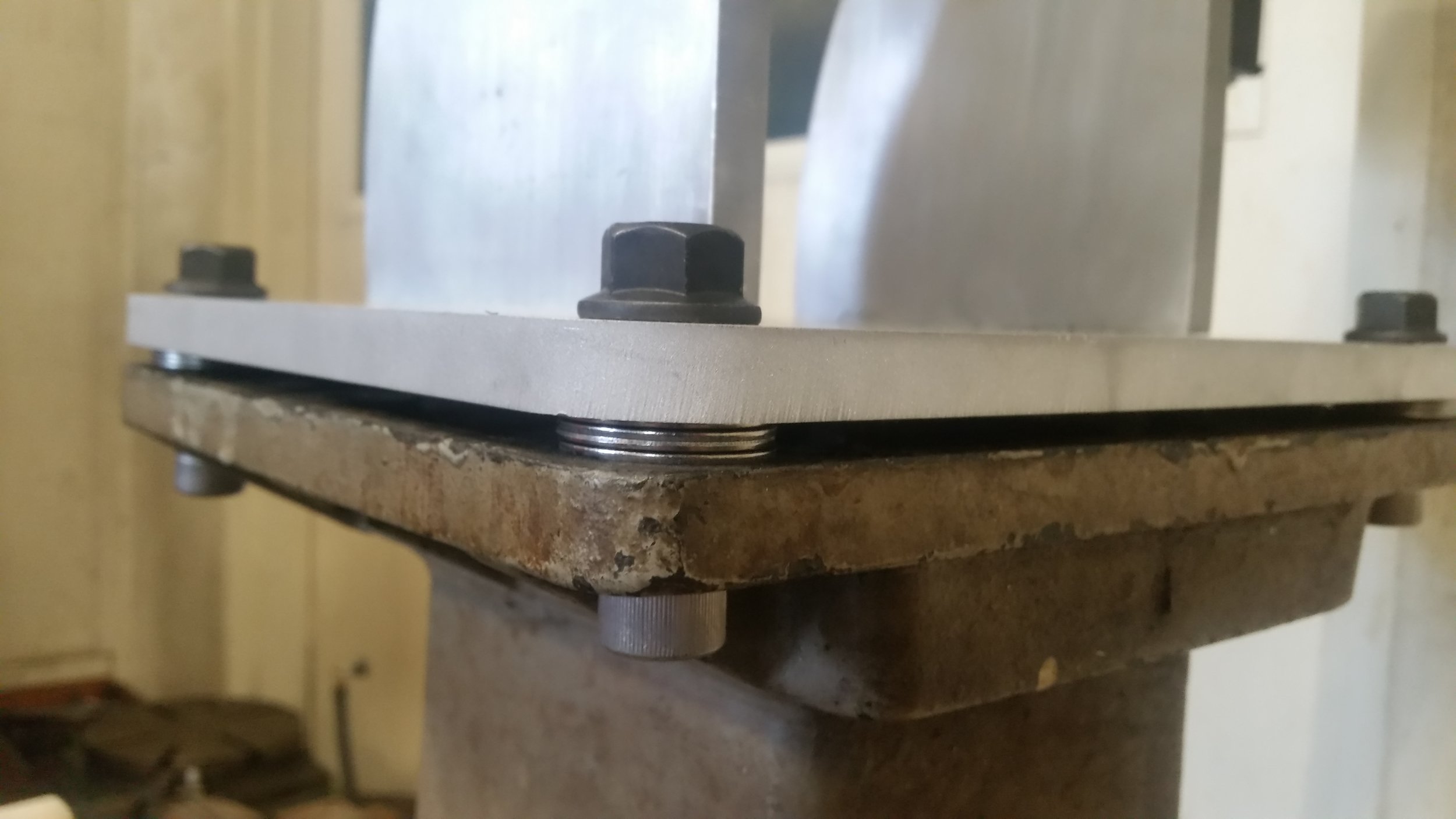
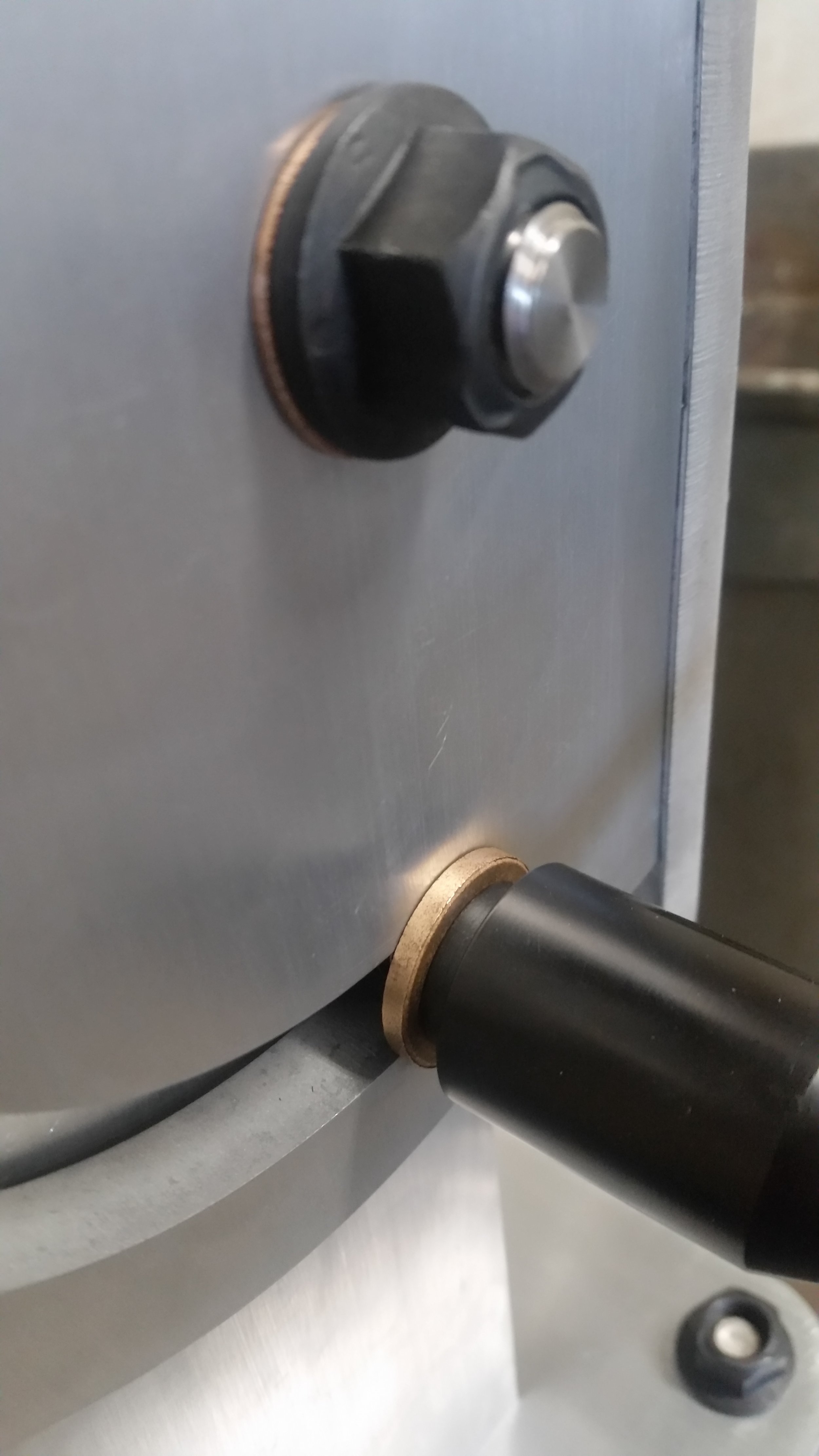
  • With the base and back plate together I then assembled the pivots. This proved tougher than expected, largely because the washers kept falling out. Not a big deal, but if I were doing the build again I would absolutely print a small fixture to hold then in place.

  • At this point it was easy to add the tension-arm, vertical and horizontal arm plates, and various knobs. The grinder was then moved to its final spot on the Stanley pedestal and screwed down.

  • Getting the motor on took two people (my thanks to Nathan Barton), and might have been easier at an earlier step, though I suspect it would have been “fun” at any point in the process.

Water Jet:

This was my first water jet project, so I was very excited to try it out. All of the structural plates were cut to dimension on the water jet. For the holes, I used the water jet to cut pilot holes and then drilled/tapped/reamed them afterwards with a drill press. The process was virtually painless, and I would certainly consider it in the future for low tolerance / non-cosmetic parts.

The plates were organized into two panels, each 1’ by 4’, to correspond to the 1/2in aluminum stock I purchased for this project. This didn’t leave me quite enough stock to completely build a second grinder, but did provide a nice buffer in case of accidents or for fabricating multiple bases as needed.

20190521_130053.jpg

Drill Press:

Playing with the main shop’s new laser guided drill press. Turns out the lasers need careful alignment before use, but it’s a neat idea.

Playing with the main shop’s new laser guided drill press. Turns out the lasers need careful alignment before use, but it’s a neat idea.

Although the water jet is great for cutting profiles, it just doesn’t have the precision for tight tolerance holes, particularly not where they need to act as bearing surfaces of any kind. To provide better hole tolerances I drilled out all of the water-jet holes on the drill press. The 1/4in holes were cut at 1400RPM with standard jobber bits from Mccmaster, and the 1/2in holes were cut at 750RPM using the same type of drills. The 3/4in reamed holes were drilled/reamed at 550rpm. That seemed to be a bit fast for our tooling, but worked well enough in the end.

A special shout-out to the main ME shop for picking up some 3/4in reamers without which this would all have been much more difficult.

The vertical arm plate. I find that writing the intended operations directly on the plates helps cut down on confusion.

The vertical arm plate. I find that writing the intended operations directly on the plates helps cut down on confusion.

All of the pivot plates (and the vertical arm plate) before drilling.

All of the pivot plates (and the vertical arm plate) before drilling.

Manual Mill:

The two pivot legs, and two pivot plates, all mount to their respective bases using 1/4-20 holes drilled and tapped into their bottom edges. This will hopefully give me a nice clean interface without taking up too much space or resorting to adhesives. Both parts were designed with a flat reference edge, which I used to align each part in the vise. I then established a reference zero on the (+X, +Y, +Z) corner with an edge-finder and drilled the 4 tap-drill holes on each part. The threads were cut by hand with the part still on the machine.

Story: While spotting my final set of holes the HSS drill snapped off in my part. I was subsequently able to simply cut through the remains of the bit using a 1/4in carbide endmill. I consider this sequence of events to be a lesson in both the hardness of carbide, and the importance of purchasing quality tools.

Using one part as a crude 90 degree reference for another. The copper block is to ensure only one of the two parts is clamped when tightening the vise.

Using one part as a crude 90 degree reference for another. The copper block is to ensure only one of the two parts is clamped when tightening the vise.

3D printer:

Although not strictly required for a test fit-up, I decided to 3D print a few of the fiddlier tension and hold-down components to get a better sense for how everything will go together. These parts need to last through a few fit-ups, but shouldn’t see more than 3-4 hours of actual grinding use. With that in mind, I printed them with my standard settings (20% infill, .6mm walls, .2mm layer height) and all of the threaded holes enlarged to take heat set inserts.

ME/EE72: Hull Panels V2

The left outer panel shortly after machining, but before the bronze bushings had been pressed.

The left outer panel shortly after machining, but before the bronze bushings had been pressed.

Our second round of hull panels was largely the same as our first round. In part because we were satisfied with our first robot’s performance, and in part because we wanted to maintain parts compatibility between robots. With that said, there were a few substantial improvements to the design and fabrication process. In articular, we expanded our use of issogrids to substantially reduce part weight (without reducing part stiffness), switched to fly cutter surfacing, and made a few process tweaks to improve overall stiffness.

Overall I am very pleased with our second round of panel fabrication. We were able to cut the parts to tighter tolerances, with no scrapped parts, in about half the time.

IsoGrid:

One of the big focuses for the second generation panels was weight savings. In order to accomplish this, we replaced the previous (much wider) pocketing pattern with a true issogrid. This reduced the weight from 1.25'lbs to .8lbs, and brings the outer panels to just under 50% volumetric metal removal.

We cut the iso-grid in two stages. First, the triangles were all roughed using a 1/4in endmill. This removed the majority of the material. Then the corners, and some of the smaller pockets, were finished using a 1/8in endmill. Both operations used HSMworks 3D adaptive operation with no stock to leave. The second operation was configured for rest machining and also removed the 20thou radial stock to leave from the first operation. Each operation took about 1:20 with fairly conservative feeds and speeds.

One very substantial time saving for this round of panels was the switch to all carbide tooling. For the 1/8in endmill that meant a nearly 6x increase in volumetric metal removal over the HSS endmill we used for our first round of panels.

Although the operations themselves were fairly time-comparable to the larger weight reduction pockets from our first robot, I should note that the CAM was significantly more time intensive. In particular, selecting all of the faces to be cut caused significant slowdowns and periodic crashes in Solidworks.

Cutting the iso-grid did not seem to increase warping. If anything it may have contributed to a reduction in warping relative to our much larger lightning panels from the first round of plates.

Overall I will certainly re-use the pattern when weight budgets are tight.

Surface Finishs:

Thoughts:

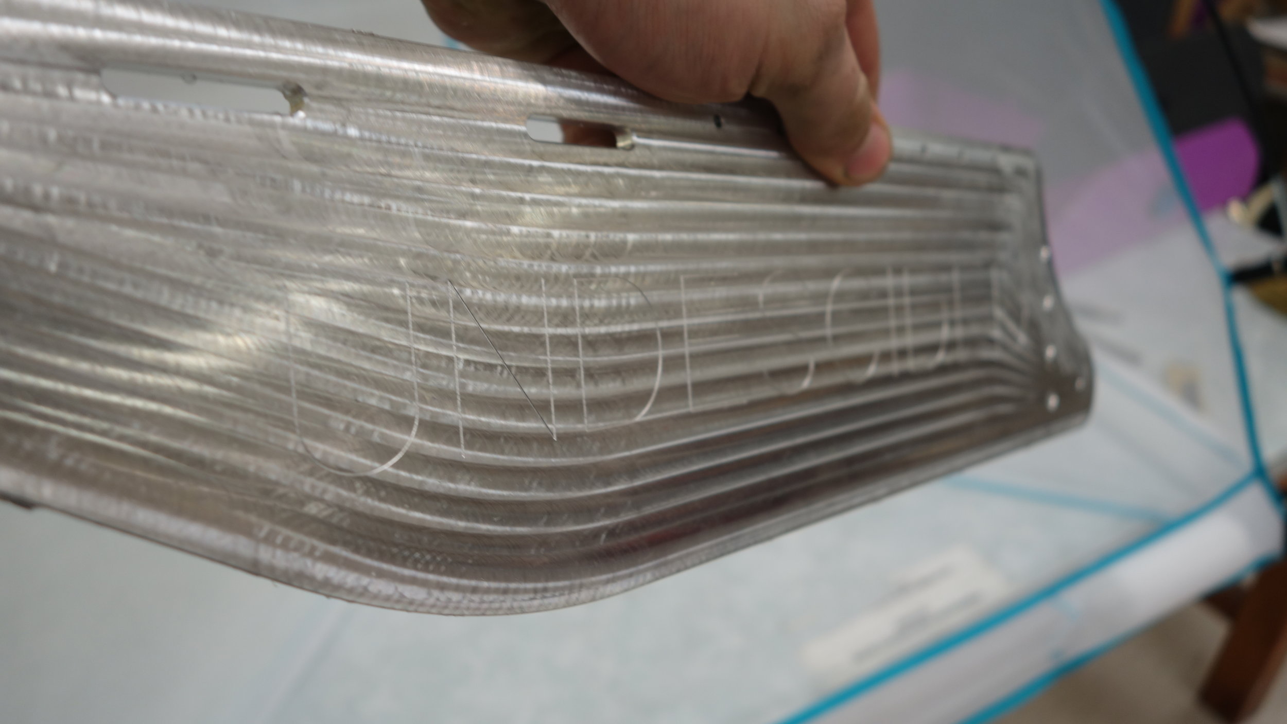
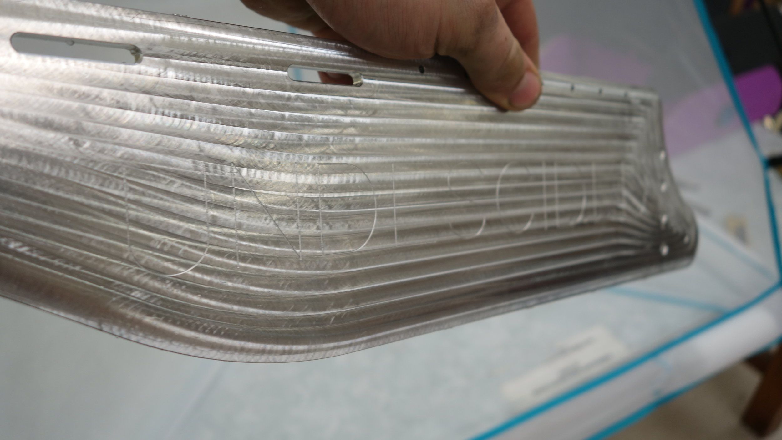
For this round of outer plates, we decided to experiment with fly cutting rather than using the 1/2in endmill for facing. Overall I am very pleased with the results. Both the inner and outer faces seem cleaner, and the shinier surface really makes the engraving pop (see image below). Cycle times were also reduced by around 70%, even using multiple passes.

We got some smearing with all of the recipes we used (see results right), but even so I like the results well enough to use the superfly for future projects. Of the recipes we tried, I think 5 was the best overall.

For the inner panels, which were faced with the same 1/2in endmill we used on robot A, we decided to try a brushed look. The parts were cut exactly the same way as last time, but were then run over a medium Scotchbrite pad. The results were definitely not as shiny as an unmodified machined surface, but I think the look was a bit cleaner overall. The brushed look did seem to hide subsequent scratches slightly better than the flycut surface we used for the outer panels.

Experimental Results

All cuts taken with a 2.5in Tormach SuperFly, with a 2” stepover, running 2500RPM and 30IPM.

  • 7 thou, 3 thou, engrave.

    • Looked good, slight smereing, crisp lines, raised a small bur.

  • 7 thou, 3 though, engrave, .5 thou

    • Looked good, slight smearing, crisp lines, no burr.

  • 7 thou, 3 tthou, engrave, 0 thou

    • Looked okay, significant smearing, no burr.

  • 10 thou, engrave, -.5 thou

    • Looked Poor, significant smearing, smeared lines, some burr.

  • 10 thou, engrave, .5 thou

    • Looked Great, minimal smearing, no burr.

The robot’s outer surface after fly cutting and engraving. I think this combination really pops well, and will certainly re-use it where visual is a top priority. One thing to note is the sharp vertical lines between passes. Those were reduced on th…

The robot’s outer surface after fly cutting and engraving. I think this combination really pops well, and will certainly re-use it where visual is a top priority. One thing to note is the sharp vertical lines between passes. Those were reduced on the Fadal (which is better trammed), but still suggest that running passes long-wise might be better for future parts.

The right inner panel after machining and “brushing”. The machining marks are still clearly visible, but I think the effect is a bit more subtle than a straight machined surface.

The right inner panel after machining and “brushing”. The machining marks are still clearly visible, but I think the effect is a bit more subtle than a straight machined surface.

Tolerance Improvements:

Surface Flatness:

Our last round of hole panels was plagued by flatness issues (on some parts we were out by as much as 15 thou). For this round we made a few critical changes. First, we re-designed the surface plate to allow for machining the entire top surface of each blank. This allowed us to fully remove the skin from each part which seems to have helped reduce twist by around 60%. Second, we planned in 0.030in of surfacing. This gave us considerably more wiggle-room for facing both sides flat.

Our results were still not perfect, but we held to our 5 thou flatness and thickness tolerances on all 5 panels (3 thou on thickness, and 5 on flatness, measuring with a height gauge on the surface plate). For the most parts the solutions we implemented were things we knew about before starting the first batch, so I think the lesson here might be that it pays to start off with a better process when possible.

Hole Tolerances:

Not really a full investigation of boring as an alternative to drilling. Did some inspection with gauge pins just to see what we are getting, and I’m going to leave the results below for future reference.

  • Counterbores - Rated: .2188 Actual: .221-.222, Variance: Minimal

  • Rear pulley hole - Rated: .1590, Actual: .160 - .161, Variance: N/A

Getting a vertical dial indicator really helped improve our process for surfacing the parts.

Getting a vertical dial indicator really helped improve our process for surfacing the parts.

Being able to “see” the thickness variations and bowing made it much easier to decide where to spend our extra material.

Being able to “see” the thickness variations and bowing made it much easier to decide where to spend our extra material.

DSC03432.JPG

Fabrication Pictures:

Taking a shot at chamfering both sides without a relief cut. This had the unexpected effect of actually raising a larger burr than would otherwise have been present. Not a great idea as-implemented but maybe an area for further experimentation.

Taking a shot at chamfering both sides without a relief cut. This had the unexpected effect of actually raising a larger burr than would otherwise have been present. Not a great idea as-implemented but maybe an area for further experimentation.

Sometimes you need a tool extender… Sometimes the best tool extender in the shop is a TTS collet holder… It worked?

Sometimes you need a tool extender… Sometimes the best tool extender in the shop is a TTS collet holder… It worked?

The Haas’s tramming error is particularly notable during facing operations. In practice we did not find the ridges compromised water-sealing so it was largely a non-issue.

The Haas’s tramming error is particularly notable during facing operations. In practice we did not find the ridges compromised water-sealing so it was largely a non-issue.

As zeroing setups go I can’t say this is my favorite, but the 1-2-3 block is only out by a few tenths, and it did work well.

As zeroing setups go I can’t say this is my favorite, but the 1-2-3 block is only out by a few tenths, and it did work well.

The ME shop’s vertical bandsaw was down so we used the student shop’s instead.

The ME shop’s vertical bandsaw was down so we used the student shop’s instead.

A blank after being cut and milled to size. The sharply definitely helped cut down on fixturing errors.

A blank after being cut and milled to size. The sharply definitely helped cut down on fixturing errors.

[Interhouse] Laminar Fountain - 2019

The arches as viewed from the dance platform. You can see where the inner illumination hits the stream breakup right before the arch.

The arches as viewed from the dance platform. You can see where the inner illumination hits the stream breakup right before the arch.

Summary:

This post covers the design and construction of two laminar flow nozzles with LED lighting. The two units have a throw of around 10’ and, with the exception of our outlets, are made from materials that can be easily sourced at home-depot and an aquarium store of your choice.

This was my 2019 interhouse* project, which I co-lead with Jack Caldwell. The overall theme of the party was “bio-luminescent world” so the two nozzles were installed with RGB LEDs over the entry bridge to Blacker’s dance platform. Overall, the fountains seemed to be very well received. Early on in the party they were a popular photo spot, and people were playing with one or both of them pretty much constantly throughout the party (see the video for what that looked like).

Collaborators:

The best part of any interhouse is always getting to work with other moles on a project of mutual interest. I was delighted to work with the following fellow students.

  • Jack Caldwell (co-lead)

  • Brittany Wylie

  • Harrel Dor

  • Gracie Suenram

*An annual event which, in Blacker, falls somewhere between a party and a tech-demo.

20190427_223351.jpg

Outlet:

The outlet of a laminar flow fountain is a bit odd. Since the goal is to minimize turbulence, you actually want to design it with the cleanest, roundest, sharpest inlet edge possible. Then you want the rest of the nozzle designed such that the water doesn’t touch the walls (frequently this results in a sort of inverted cone geometry).

We went through a number of designs before ultimately settling on CNC machined inserts set into 3D printed inserts. The large outlet cap for our nozzle holder takes 12 hours to print, so using a modular design helped us keep the printing time per test down to a much more reasonable 1.5hrs per part. Both the nozzle holders and outlet caps were 3D printed on either the school printers or my own machine. To help with waterproofing, I increased the floor, wall, and scieling thickness to 1.8mm, and upped the infil to 95%. We also found that using 3D infills (any of the ones based around printing cells) worked better than 2D infills, though the difference was not substantial. Some of our rushed 3D prints did leak, but the ones we printed on-spec and on-speed never leaked. The parts were sealed against each other using marine grease for testing (which sort of worked) and using super glue for the final fitup (which also sort of worked, but didn’t require clamps). We used 4-40 threaded inserts for the outlet cap to nozzle holder interface.

Note: Our first quick-swap system used a female threaded pipe cap, and 3d printed threaded inserts. This may or may not have been sufficient, but we moved away from it out of a concern that the threads were disrupting flow and limiting our performance.

The actual nozzles were cut on our Fadal VMC15 out of 1” aluminum stock. The central hole was bored to 5/16 using a 1/4in carbide endmill, and the counterbore was bored to 3/4” with the same endmill to prevent the stream from contacting the walls. On some of the nozzles the outlet hole was then counterbored to reduce the walls to a sharp point, while on others they were left at their full 0.1” length. The water seems to neck sufficiently to avoid the full 0.1” nozzle length and thus both geometries performed equally well. In the hope that it would produce a better edge (which under a microscope it certainly did) we lapped two of our 3 nozzles. However, while this did improve the edge it did not improve performance so it may be that we were limited in other areas.

Note: I am happy with the final performance of our nozzles, and would use design #1 (short bored section followed by a 45 degree chamfer to a much larger bored section) again without reservation. However, we also found that lapped washers performed similarly as long as they were both ID and surface lapped. This may be a more economical option for you if you are trying this project without access to a machine shop. A list of the other things we tried can be found below:

Nozzle Methods Tried:

Each Nozzle was turned from round stock to (very) rough dimension. The lathe-faced side was then placed face down (see above) with a single parallel under the part for reference. The setup was then tightened and the parallel was removed. I found thi…

Each Nozzle was turned from round stock to (very) rough dimension. The lathe-faced side was then placed face down (see above) with a single parallel under the part for reference. The setup was then tightened and the parallel was removed. I found this setup to be sufficient for our purposes, and plan to use it for future insert cuts.

3D printed: This actually produced a great nozzle for almost all of the circumference of the anulus. Unfortunately, we were never able to get rid of the blob when the printer transitioned from the innermost line to the one just outside of it. As a result, performance deteriorated quickly past a 2’ throw*.

Laser Cut: Worked Spectacularly worse than the 3D printed nozzles, it seems the laser cutter introduced a small burr on the bottom side of the cut. After polishing that off it did work better than the 3D printed nozzles and could be promising long term. The process was very fiddly though so we moved on in the hopes of finding a more repeatable option.

Drilled Acrylic: Worse than the laser cut acrylic in every way. I would not try this again, a Delrin or HDPE sheet might work better though.

Unprocessed Washer**: This was our first strong performer. Flow remained laminar out to about 4’ - 5’ depending on the washer. Though there were some washers where it broke up immediately, so it’s important to insped each washer before use.

Lapped Washer: Lapping the washers on a flat surface and then ID lapping them significantly improved the consistency of our results. This is where we started to become limited by other factors in system rather than the nozzle. I would personally suggest going with this option unless you have easy access to a CNC mill or CNC lathe. It is however, fairly time intensive because a lot of material had to come off to get flat parts.

CNC Machined: Performed slightly better than the washers, and were much faster to make. We turned the blanks on a lathe out of 1” aluminium rod stock and then processed the actual nozzle geometry on our VMC15. Lapping the inlet surface improved surface quality, but not in a way that seemed to matter.

*all ranges given at roughly 45 degrees of elevation.

** None of our washers were stainless. This was fine for testing, but I’d strongly suggest getting a stainless washer if you want more than about 20 minutes of run time.

INLET:

We designed our inlets to generate a rotating flow in the first chamber of the nozzles. The idea was that this would better spread the water over the whole inside of the nozzle rather than concentrating it in one area. It also allowed us to print our inlets with a small cylindrical body in the center to hold the acrylic rod and LED. The inlets were printed as a single piece and took about 16 hours each. On the whole they worked fairly well, although I think some kind of self-contained tightening system to tension against the outlet caps would have helped during the prototyping phase.

In the interests of full disclosure I should probably note that this is one of the areas where we did the smallest amount of experimenting. We tried axial flow early on, but switched to radial based on the internet consensus and then never really tweaked the design. We got good dividends from the areas where we choose to focus our efforts, but I think the inlet would be a good area for experimentation on future builds.

Flow Straightening:

The flow straightener without optical bypass. I think the rough top screen and straw twist contributed to the poor performance of this unit. With that said, resolving those issues only marginally improved overall laminar throw.

The flow straightener without optical bypass. I think the rough top screen and straw twist contributed to the poor performance of this unit. With that said, resolving those issues only marginally improved overall laminar throw.

The design we settled on was two pair of 2in disks of aquarium foam spaced by 5.5in and set about 1.5in back from the outlet. We sank, by far, the majority of our prototyping time into the flow straightening system, but I think it remains our biggest area of potential improvement.

In particular, most of the high performance systems we have seen online use straws, or some kind of straw analogue, to artificially lower the renynolds number in the pipe and create laminar flow. We originally started out using straws, and tried a number of different sizes and lengths of straws over the course of our build. Overall, we found that smaller and more consistent lengths, perform better than longer, or less consistent lengths. However, the effect was pretty small (though any straws performed better than no straws).

One possible reason for our poor performance could be our use of a “straw carrier”. These were 3D printed housings that allowed the straws to be packed externally and then inserted into the pipe as a unit. From a fabrication standpoint this was great, but it is possible that the irregular patterns designed into our straw carriers contributed turbulence to the system which then fowled the clean stream from the straws.

The two nozzles we deployed differed slightly in that one used a straw carrier (with straws) to space the two layers of aquarium foam, while the second left that area blank. We so no significant difference in performance between the two units and suspect that the straws were completely canceled out by the foam.

Lighting:

Control:

Our LED control board. It held up well during the part, though the power input connector was damaged during take down.

Our LED control board. It held up well during the part, though the power input connector was damaged during take down.

The electronic for this system were quite simple. An Arduino Nano was used to control two 9W RGB LEDs from Adafruit. The LED brightness was set with a pair of 20 ohm resistors on each channel, and a pair of ULN2803s provided the current capacity required to run each channel at 500ma. For LED connectors, we used some 5 pin molex connectors (because that is what I had) and for main power we used an XT60 connector directly soldered to the board. This system worked well, except that it was short on PWM pins so not all of the channels had brightness control.

The pattern we ran used a fair number of blue/green fades with with the occasional switch over to red/purple. This worked well, though I am certain there are more options to explore.

Block diagram for the LED control board. It should be noted that the nano only has 6 PWM channels so it is necessary to either use some channels as full on / full off, or to use software PWM for some colors.

Block diagram for the LED control board. It should be noted that the nano only has 6 PWM channels so it is necessary to either use some channels as full on / full off, or to use software PWM for some colors.

LED cable wiring diagram, included here for future reference.

LED cable wiring diagram, included here for future reference.

It’s hard to find a pinout for the PSM-ISR950EP online, so I’ve drawn this up for future reference. There are a few pins whose purpose I have not yet determined, but I’ve got enough to use the model for stuff like this.

It’s hard to find a pinout for the PSM-ISR950EP online, so I’ve drawn this up for future reference. There are a few pins whose purpose I have not yet determined, but I’ve got enough to use the model for stuff like this.

Power:

The power supply for this project was a PSM-ISR950EP server power supply pulled from E-Waste several years ago. After a bit of sleuthing I was able to get it running, and found that it was way more than adequate to run our two 9w LEDs. Putting an XT60 connector on a 5v rail did feel a bit weird, but I think it was better than using alligator clips or some bandanna plugs (the other two medium-current connectors I have on hand).

We ended up placing the power supply behind the fountains, outside of the flooded area, and then running the 5v and ground wires over to the fountains in a pair. Putting the power cables in the water was not an ideal choice, but certainly much preferable to having 110AC suspended over the water.

20190427_151107.jpg

Light Pipes:

We made the decision early on to place our LEDs outside of the housings and move the light into the nozzle with a light pipe. This saved us from having to worry about waterproofing the LEDs, and also gave us a bit more flexibility on our timeline. We used 1/2in by 10in acrylic rods as our light pipes. These were inexpensive, and seem to work reasonably well for transmitting the light once it has entered the rod.

The one major issue we ran into was coupling. The LEDs we choose have a domed geometry that creates a very braud distribution of light. This means that with flat ends we were really only getting 30% - 40% of our light into the tubes. This was especially clear comparing the 300 Lumen LEDs to a 150 Lumen flashlight. The Flashlight produced a much brighter stream despite a lower total power output. After reading through some industry documentation on light pipes (and talking to an alumn who works in optics) we ended up drilling a small hemispherical hole in the inlet of each rod and then epoxying the LEDs in place. This increased overall performance slightly, and made the rods easier to handle and install (since they were now single integrated units. We also wrapped each rod in Teflon tape in the hopes of improving transmission, but it is unclear if this had an impact.

The as-of-party performance was pretty solid, with a nice lit up section at the peak of each arch. I am happy with the results, and think that other improvements (like special effects or more quantity) would produce greater dividends for future builds. With that said, a switch to real fiber-optics, or maybe better pre-tube focusing would likely produce a dramatic increase in transmission.

A note on resistors: The electronics for this project took place on pretty short notice, so I ended up using 1/4w resistors for all of my current limiting. With two 20ohm resistors in parallel sinking 500ma this works out to about 1.25w per resistor. I strongly recommend against doing this. However, I did run several tests and even running full brightness we were fine for the ~20hr design life of the board. If you are making this project with more time to spare please just purchase correctly rated resistors.

Doming the input and then using epoxy helped us capture more of the LED’s light flux. The paper we read suggested we should get a 80% or so improvement. In practice I think it was more like 20%-30%, but still substantial. (Also human vision isn’t gr…

Doming the input and then using epoxy helped us capture more of the LED’s light flux. The paper we read suggested we should get a 80% or so improvement. In practice I think it was more like 20%-30%, but still substantial. (Also human vision isn’t great for scaling brightness differences so it’s hard to know for sure)

Sustained testing (10hr/day for 8 days) resulted in no performance drop from submerging the LEDs. There was some electrolysis going on at the contacts, but there did not seem to be any significant contact degradation as a result (over our relatively…

Sustained testing (10hr/day for 8 days) resulted in no performance drop from submerging the LEDs. There was some electrolysis going on at the contacts, but there did not seem to be any significant contact degradation as a result (over our relatively short test). I would not suggest using this kind of setup for a long term installation, but for something that only needs to last a few hours or days it could be a good option.

Fluids:

Water for our fountains was provided by two pool drainage pumps: a 1/4hp pump which has been in the house for many years, and a 1/3hp pump purchased for this project. The fountains were set up inside a flooded basin which provided the water-return for the fountains, and was a substantial interhouse project in it’s own right (our thanks to the flooding team for letting us set up in their installation).

A rough sketch of the water flow through our system. It should be noted that the line running to the second nozzle was about twice as long as the line to the first (hence the need for an equalizing clamp).

A rough sketch of the water flow through our system. It should be noted that the line running to the second nozzle was about twice as long as the line to the first (hence the need for an equalizing clamp).

Water straight out of the pumps has a fairly jittery pressure head, we did not measure the pressure, but I would guess the jitter was around 1khz. Left unattended, this turned into lower frequency pressure variation in the nozzle and degraded fountain output. To resolve this issue, we installed an 8’ section of vertical 4” pipe, capped at both ends, as a low pass filter. Both pump inlets were positioned at the base of the filter, with the two fountain outlets, and the pressure relief valve were positioned about 8” higher up the tube. This did a good job of filtering vibrations from a single pump during testing. However, it was less effective (though still sufficient) with the two pumps both running. It seems as though it may do a better job of catching the higher frequency variations from the 1/4hp pump than from the 1/3hp pump.

Though not a perfect analogue, it may be helpful to think of this system as an RLC circuit. With the tube having many of the properties of a capacitor (the water is pressurized against a “spring” of air, giving the tube storage additional storage capacity with pressure), while the lines behave a bit like resistors (in that they reduce pressure flow) and inducters (in that there are momentum effects from the flowing water). This was not a major focus area for us this time around, but I look forward to more fully exploring this system in the future.

The overall water flow through the nozzles was tuned using a ball valve connected directly to the low pass filter. This let us bleed off pressure and helped keep the arch-lengths to something reasonable (such that the flow would remain mostly laminar). To equalize throw lengths between the two nozzles a clamp was placed on the tubing running to the closer nozzle, and then tightened until the pressure drop along both nozzle supply lines was roughly equal. This worked well, but required about 10 minutes of hand tuning to get right.

Budget:

Our original budget for this project was 275$, of which we spent about 315$ (this was not a budget we were expected to adhere to). Our largest single cost was the new pump, with much of the rest going to prototyping and brass fittings. The control electronics and power supply are not included because I either had them already (power supply) or purchased them separately (arduino). Not including prototyping costs, we ended up spending about 25$ per nozzle in final parts.

The most significant areas for cost reduction are likely the brass fittings (4$ at home depot, 1.5$ online) and the vinyl tubing which is cheaper in bulk, or which could be replaced with hose at lower cost.

IMPROVEMENTS for next time:

Use a collar or other quick-connect mechanism for holding the two ends on. This would make it much easier to prototype. Something based around 1/4-20 cap screws would be good because you could then use an impact driver to set it up and take down.

Real fiber optic is not that much more expensive than the acrylic for small numbers of fountains, and seems likely to work much better. For fountains where light is a priority I would absolutely make the switch. On the other hand, for fountains where bulk is important or where other effects are the focus then the current design works well.

Resources:

Testing Pictures:

Testing maximum flow rates with one of our earlier nozzles.

Testing maximum flow rates with one of our earlier nozzles.

Unintentionally siphoning off the water test bucket through the nozzle. After this we started placing the nozzle above the level of the water, but it was fun to see this in action.

Unintentionally siphoning off the water test bucket through the nozzle. After this we started placing the nozzle above the level of the water, but it was fun to see this in action.

Some early testing with our 6” nozzles. You can see that the nozzle was hooked directly up to the pump with no filtering.The pipe-clamps let us change the internals relatively quickly, without a great deal of fuss. Overall I liked the design, though…

Some early testing with our 6” nozzles. You can see that the nozzle was hooked directly up to the pump with no filtering.

The pipe-clamps let us change the internals relatively quickly, without a great deal of fuss. Overall I liked the design, though I’d probably build some threaded rods into any new future nozzles to serve the same purpose.

Appendix A:

I have been getting some questions about where exactly to hook up the enable jumper for the supply, so I’ve added this picture to clarify. The connection should be from the top right pin to the bottom left pin as shown above. You can use a plain jum…

I have been getting some questions about where exactly to hook up the enable jumper for the supply, so I’ve added this picture to clarify. The connection should be from the top right pin to the bottom left pin as shown above. You can use a plain jumper or switch depending on your preference, but do note that they pads can be a touch delicate so you want more strain relief (and insulation) then is shown in the test setup above. As always, don’t hesitate to reach out (use the contact form under “about”) if you have any questions.

[knife making] rough spine camp knife

Summary:

The knife after sharpening, but before the last few touchups to the oxide layer on the spine and blade.

The knife after sharpening, but before the last few touchups to the oxide layer on the spine and blade.

This is a short handled bush/camp knife. It is a bit shorter, and a bit wider, than my last bush knife, and is designed to have a bit more of a rough-finished look too it.

The blade was cold-peened to give it a textured look, and then the mill scale was left in place after heat treat to help give the knife a darker aesthetic.

For the most part this knife came out well. I really like the cold blued aesthetic for the spine, and peened blade. This was my first time hand sharpening a knife using a wetstone, and I think that worked well from a sharpness perspective. With that said, the edge ended up being a bit too thin, so I plan to dial that back, or maybe add a micro-bevel.

Update: This knife’s blade did not hold up well to chopping through wood. In talking with more experienced knife makers it seems like my temper temperature was likely too high (450F, rather than 400F) and that I needed to do a full body quench shortly after the edge quench to prevent retained heat from softening the edge and bevel.

The knife just after final touchups and sharpening. You can see that the silvery bits along the spine are now gone.

The knife just after final touchups and sharpening. You can see that the silvery bits along the spine are now gone.

ME/EE72: Fixturing Improvments

DSC03432.JPG

Summary:

Before beginning the second round of CNC fabrication, we fabricated two locating blocks, and added counterbored holes to our side panel fixture plate. This made the plate much easier to set up, and dropped our fixture setup time from around 30 minutes to around 5. We also added set-screws to the unused 1/4-20 holes. This didn’t really improve setup times but did make cleaning easier.

Update 4/17/2019: Adding the tramming blocks and flush mounting bolts was a fantastic ideas. I have used this fixture for easily 7-8 medium-low tolerance parts and consistently held 1-2 thou with no tramming.

Traming Blocks:

To make Traming a bit faster, I made up two blocks to locate the fixture plate against one of the T-Slots. The idea being that with the blocks pressed against the T-Slot, and the fixture plate pressed against the blocks, the entire setup would be trammed without any additional alignment. In practice, the plate tends to move by 4 thou or so when being tightened down so there is still a bit of tapping in required. Still faster than without though.

DSC03414.JPG

Fabrication:

In the first setup, the stock is clamped in the middle of the vise by the lowest 1/8in of the stock. The top geometry, outer profile, and engraving are then cut with a 1/2in endmill and 20 thou ballmill. The part was the flipped and placed with the retention ridge against the edge of the parallels. The top 130 thou was then faced off to produce a squared part with all 6 (or 10 depending how you count) sides faced.

Reflections:

Overall, not huge time savings. Learning how to tram properly (tighten one corner than tap the other) made a much bigger difference. Still, it was a good way to turn low value time at the beginning of term into high value time later on. Would do it again in a similar situation.

ME/EE72: Hull Panels V1

Overview:

The right rib partially assembled.

The right rib partially assembled.

This post outlines the fabrication process for our side panels, which run the length of the ship and provide mounting geometry for most of our land mobility systems. The side panels are made from 6061-T6 aluminum, and all four were cut on one of the school’s VMCs using our fixture plate from earlier in term.

Making the side panels was easily the most time consuming portion of our fabrication process for Frog A, requiring over 70 hours of reserved CNC time. With that said, the majority of that time was spent checking cuts, tweaking setups, and repairing/replacing errors in prior runs. All told the 4 plates only have around 8 hours of actual “cut time” so I am hopeful that we will be able to reduce fabrication times substantially moving forward.

All four of the side panels prior to assembly.

All four of the side panels prior to assembly.

The right rib, post assembly.

The right rib, post assembly.

Cutting the Faces:

The fixture plate and prepared blank on our Fadal VMC15 before the first operation.

The fixture plate and prepared blank on our Fadal VMC15 before the first operation.

Setup:

Each side panel was cut out of a 19.5” by 5” by 0.25” blank of extruded aluminum bar stock. The stock was purchased from online metals in 6’ lengths (to reduce shipping costs) and then cut to rough size on the shop’s horizontal bandsaw. One 5in edge edge was then finished on a manual mill to provide the two reference corners for the part. The part edges were then deburred on a Scotchbrite wheel, and the two reference corners were marked with Sharpy.

Tabs helped increase process reliability and came off easily using the bandsaw.

Tabs helped increase process reliability and came off easily using the bandsaw.

Fixture:

We set the work coordinates for this part to be the top rear left corner for the first operation, and the top front left corner for the second operation, with the part about it’s long axis. This meant that we were using the same physical corner as our zero for both faces, thus eliminating the risk of errors due to irregularly sized stock. The tools were measured from the center of the workpiece using the shop’s 4in height guage*. In some cases it was necessary to lengthen the tools slightly to ensure that they were able to reach the bottom of the parts given our short fixture plate. We also found that some of the operations raised burrs on the non-part portions of the stock. We solved this by sanding them down, but I think moving to facing the entire top of each part would be a good idea for round two.

The blanks were held using our 5in fixture plate, and tensioned with 1/4-20 miteebites, spaced with some copper shims as needed to accommodate thickness variations in the stock. This seemed to work well, and I would certainly re-use a similar fixture for future panels and flat parts in general. We did find that with the thin (1/8in) edges on some of our parts it was necessary to add tabs since the foil tended to tear when thin enough to be convenient. Tabs about 1/8in wide and 40-50 thou high seemed to be more than sufficient, though we did use several on the longer faces of the panels. These seemed to cut better than fewer larger tabs.

*Note Post Build: Our fixturing setup for round two was vastly better, I would suggest copying that if you plan to cut parts like this in the future.

Faces:

The first operation on all of the parts was to face the simpler side (inner for inner ribs, outer for outer ribs). With a slightly dull HSS endmill machining marks are inevitable (though they are less pronounced in person than in the images below). To make the best of things, I decided to use a contoured spiral to cut the outer faces. This added about 10 minutes to each outer plate, but left us with a cool pattern vaguely reminiscent of a wale. That said, it did make it a bit hard to read the engraved “Undescided” (our team name, yes that is the correct spelling) on the outside of the panels though so I plan to move to fly cutting for the next batch.

On a more practical note, the facing operations did a good job of underlining just how warped our stock is. For most of the parts we ended up having to take multiple passes to the tune of 15thou per side in order to get a clean surface. It is not clear to me exactly how much of this has to do with our fixturing/cutting methods and how much has to do with the actual stock, but it is concerning in any case.

Lightening Pockets:

Both the inner and outer panels had significant lightening pockets cut out to reduce the part weight. The inner panels had through-cut lightening holes, while the outer pockets were cut with our rough approximation of an issogrid. Removing as much material as we did proved very time consuming. The inner panels took around 45 extra minutes to cut, while the outer ones gained around 75 extra minutes. That said, we ended up being quite tight on our weight budget, so the extra fabrication time was more than worth it.

The pockets were first roughed using a 1/4in endmill, and then finished using a 1/8 in endmill to get into the smaller pockets and tighter corners. We used a conventional 2D pocketing strategy for both passes, and then cleaned up the walls with a 10 thou finishing pass. These cuts would likely have benefited from an adaptive approach, but the FADAL lacks the requisite block processing, so we stuck with simpler machining strategies.

These cuts are one of the parts of our process I am least happy with. Although the pockets turned out well in the end, we got a lot of chatter and resonance in the part while cutting. I suspect this was due to a combination of HSS tooling and long tool stickouts. I plan to use much more conservative stickouts, as well as carbide endmills, for the next set of plates.

Note: The weight budget ended up being tighter than we expected. With that in mind, the inner panel lightening holes were sufficient, but the outer panel pockets were not. I plan to remove significantly more material from the next set of plates.

20181203_160844.jpg
DSC03283.JPG

Tapped Holes:

Tapping the top holes, all of the CNC work for the edge tapping was done on the TM1.

Tapping the top holes, all of the CNC work for the edge tapping was done on the TM1.

Manually tapping some of the 6-32 side holes.

Manually tapping some of the 6-32 side holes.

4-40:

Not a setup I am exactly proud of… it did work though.

Not a setup I am exactly proud of… it did work though.

A tapped lower standoff hole. These provided the spacing and structure for the ribs

A tapped lower standoff hole. These provided the spacing and structure for the ribs

One of the more interesting parts of this design, were the vertical mounting holes. The top and bottom edges of each panel have a number of tapped 4-40 holes used to connect the plates to the hull-bottom, and hopefully used to connect the ball hardware to the plates. With several hundred holes to drill, we decided to approach them as a CNC operation, and successfully roll-tapped all of the holes using the Haas TM1. Since the first set of plates varies in thickness by 15 thou, we found it necessary to keep track of which edges were “reference edges” so that we could drill and tap the the holes relative to those edges. This required a large number of fixtures. We plan to use custom soft jaws for the next batch.

The other set of 4-40 holes found on the robot were are the standoff mounting holes. These are used to connect the inner and outer panels of each rib, and are tapped about 100 thou deep. Since we do not have a bottoming roll-tap, we chose to tap only the first turn of the threads and then chase the rest out using a 4-40 screw. This worked well and will be replicated on future builds.

6-32:

In addition to the 4-40 screws used to tension our standoffs, we also have a number of 6-32 tapped holes used for mounting the gearbox assembly’s as well as the ball handling systems (possibly). Since these interfaces had not been finalized when we began fabrication, the holes were drilled as 4-40 clearance holes and then finished by hand during assembly.

10-24:

There is a single 10-24 screw used as a shaft for the lower, rear, belt rollers. It was drilled to size on the CNC and then tapped manually at the tapping station.

An angle block for drilling the bow holes.

An angle block for drilling the bow holes.

Test fit-up of the jig for our bow holes.

Test fit-up of the jig for our bow holes.

Teflon strips were used to prevent scratches.

Teflon strips were used to prevent scratches.

Chamfers:

We used three sizes of chamfe on the side panels. see below for a summary of each. The pocket and perimeter chamfers were cut with a 1/4in, 4 flute, spiral, carbide chamfer mill, and the hole chamfers were introduced with the 5/16 HSS spot drill during the initial spotting operation. All chamfers were 90 degree.

Drilled holes on the part were all furnished with a 10 thou spot-drilled chamfer. That seemed to work well, and I would use it again. The milled pockets (lower) were milled with a 1/4in carbide endmill and given no chamfer.

Drilled holes on the part were all furnished with a 10 thou spot-drilled chamfer. That seemed to work well, and I would use it again. The milled pockets (lower) were milled with a 1/4in carbide endmill and given no chamfer.

The test-part was given a 40 thou chamfer on both sides. This was by far our prettiest option, but ended up cutting into the available edge space a bit too much.

The test-part was given a 40 thou chamfer on both sides. This was by far our prettiest option, but ended up cutting into the available edge space a bit too much.

The 4 production parts were given a 15 thou chamfer on all edges. This worked well and looked good. Although, as you can see, we did get some chatter towards the inside of the part.

The 4 production parts were given a 15 thou chamfer on all edges. This worked well and looked good. Although, as you can see, we did get some chatter towards the inside of the part.

3D printed Potato Cannon Rounds

The cannon firing a pineapple during the same series of tests… It mostly just exploded.Photo Credit: Brian Cruz

The cannon firing a pineapple during the same series of tests… It mostly just exploded.

Photo Credit: Brian Cruz

Goal:

Blacker house has a potato cannon (pictured right) which we roll out during rotation, and then sporadically throughout the year. Naturally, we have tried firing many things out of the cannon which are not strictly speaking potatoes, generally with entertaining results. However, it has historically been somewhat difficult to launch powdery or liquid materials without making a gigantic mess inside the cannon. This project aimed to change that.

To be a bit more specific, a good potato cannon round must:

  • Fit inside the cannon.

  • Survive launch.

  • Carry a reasonable payload.

  • Break up into small enough pieces not to pose a hazard to viewers.

  • Be easy and inexpensive to fabricate.

Fabrication Documents: CADs

Experiments:

Process: The goal of this project was to generate a good design for a water round for the cannon by varying the parameters of our model. To that end, we printed 30 rounds with varying designs (see below), and fired them at a plywood target. To get a sense for when and how rounds failed we collected the fragments after each firing and, when needed, recorded video of the round being fired. All of the rounds used for data collection were filled with water and caped with hot-glue and the standard cap disks. However, we did also fire rounds containing dry ice, LN2 and ice to good effect.

Design: In an effort to maximize our strength per weight, we settled on a double-walled design, with an outer shell held onto a watertight inner shell using ribs. For the most part, the rounds were entirely wall, and thus had no infill. However, most of our rounds did have a “tip” section at the tip of the round printed at a higher infill to provide weight and reduce tumbling.

To cap the rounds, we printed a number of small disks with locating rings. These fit into the hole on the back of the rocket and were hot-glued on before firing. We found this to work quite well, with most caps apparently remaining intact as long as the rockets did.

Fabrication: Since we wanted relatively complex shapes, and relatively low fabrication costs, so 3D printing made perfect sense. All of our prints for this project were made on Nathan’s slightly modified Monoprice Ultimate. The rounds themselves were printed in “series” (below) which internally share a design. The caps were common between all designs, and were printed in batches as needed.

Top of the XD series, right below the solid cap.

Top of the XD series, right below the solid cap.

Bottom of the XD serries. You can see the added bottom chamfer.

Bottom of the XD serries. You can see the added bottom chamfer.

XB series: .8mm (2 layer) outer wall with 6 full length longitudinal ribs connecting the inner and outer walls. Top cap printed at 85% infill. Consistently survived for impact. Retired after a cap segment flew 50’ to strike a second story window. (Why the courtyard has safety glasses)

XC series: Same fundamental design as the F series, cap infill reduced from 85% to 10%. Round failed in the air well before reaching the target.

XD series: Reduced cap height to the very top of the part, added chamfer to bottom of inner chamber. Cap infill set to 15%. Most rounds failed on impact, though we believe XD13 failed mid-flight. We nave not identified what caused that failure.

XE series: Increased cap infill to 25% and increased the number of ribs from 6 to 8. Consistently survived to impact.

XF series: Increased the number of ribs from 8 to 12. Based on the denting and landing patterns we believe these failed on impact. Performance seems improved over the XE series.

XG/XH series: G had the same geometry as B/C, with a 50% cap infill and bottom fillet. XH had 65% cap infill. No performance difference. Video evidence suggests survival to impact. However, no denting could be identified on the recovered caps.

Makers Mark V1

These are a pair of wax stamps for use sealing letters. The tree is my design, and the sun was made for a friend. Both were rough-turned on the lathe, and then finished to length with a 1/4in endmill. The engraving was done using a 1/32in ball engraving mill from lakeshore carbide.

This was my first test of the stamp fixture jig from my last post, and I found that it worked very well on the whole. Total cycle times were under 7 minutes a piece including fixture time and getting the g-code loaded. This should let me iterate the design to get the correct depths and detail levels.

The two stamps, the one on the left was designed by me, and one on the right was designed by my partner, Emma Kerr.

The two stamps, the one on the left was designed by me, and one on the right was designed by my partner, Emma Kerr.

edited.jpg

Results:

From a machining standpoint, I felt the parts turned out well. The lines were crisp, and I very much like the swirling pattern I got out of my facing pass. However, the resulting stamp could use some work. In particular, the lines were much too shallow, such that it is very difficult to make out the pattern.

I was intrigued to discover that all of the detail seems to come across (provided you get close enough to see it) with every stamp. This suggests to me that while the stamp needs to be deeper and larger overall, there might be a place for more detailed engraving on future versions.

I should also probably also acknowledge that the letters on both are quite backwards. This was very much not intentional, and a somewhat silly mistake, but I do rather like it. I plan to fix it on the next version and then compare the two.

20190216_190645.jpg
My ME72 cooling block has nothing to do with this project, but it does make a rather aesthetic backdrop.

My ME72 cooling block has nothing to do with this project, but it does make a rather aesthetic backdrop.

Makers Mark: Prototype Jig

The finished jig holding a piece of of 3/4in brass. The actual work-pieces will be shorter.

The finished jig holding a piece of of 3/4in brass. The actual work-pieces will be shorter.

Purpose:

This is an engraving jig I plan to use for fabricating wax stamps, and wood brands. At the time of writing, I have completed the left side of the jig, which will be used for making stamps, and have left the right side of the jig unfinished so that I can add the proper geometry once I have finalized a brand design.

Design:

The design in it’s current form has two critical elements. The first is a large central pocket for use as a height reference. It is sized to fit our tool analog tool setter, and should make setting heights relative to the bottom of the part easy. The second critical feature is the actual part pocket. The brass hexagon is mounted on an eccentric socket head cap-screw such that it can press work pieces against jig as shown.

Precisely locating the part in this fashion takes a lot of the pain out of using round work pieces by allowing us to reference off of the included z floor, and x/y slots to get the part zero. Since the jig is rectangular, it can then be removed and returned to the vise without losing those zeros with the help of a workstop.

Note: This system works okay, but it required some tight tolerance machining and is a bit fiddly to set up. If I were making this part again I would locate the cylinder on a V, and mill a small V or ID radius into the Mitee Bite where it interfaces with the workpiece.

The piece immediately after the first operation, with the profile and lower surface cut.

The piece immediately after the first operation, with the profile and lower surface cut.

Fabrication:

The part itself is composed of 7068 aluminum, and was machined in two setups. First, the bottom was faced and the outer profile of the part was milled. Neither of these operations is critical to the final performance of the part.

Second, the pockets, tapped hole, corner relief slot, xy references and engraving were milled according to the following order. It was important that all of these features be added in one setup so that their relative positions would be as precise as possible.

Using a 0.4in gauge block to get the x axis offset. I have found this method of reaching under the “hat” to be repeatable to half a thou or so in practice.

Using a 0.4in gauge block to get the x axis offset. I have found this method of reaching under the “hat” to be repeatable to half a thou or so in practice.

  • The part was faced with a 1/2in endmill. This does not provide a critical surface.

  • The pocket was first roughed with a 1/2in endmill using an adaptive strategy and then finished with a conventional pocketing strategy using the same endmill.

  • Next, the critical pocket edges and two reference edges were cut with a 1/2in endmill using a profile strategy.

  • The corner relief slot was milled with an 1/8 in endmill using a slotting strategy.

  • A 10 thou chamfer was put on all upper edges in to break the burr.

  • The MiteeBbite hole was then spotted, drilled, and tapped to 1/4-20 x .5

  • Finally my makers mark, and the writing was engraved on with a 20thou engraving ball.

The preceding operations ended up resulting in some warping towards the height block pocket, so I then cleaned up the underside of the part on a manual mill, and debured the remaining edges with a 600grit moldstone.

[Machining] - Peg Vise

Summary:

Version 2 in all it’s glory.

Version 2 in all it’s glory.

This is a CNC machined peg-vise. I intend to use it mostly for soldering, but I suspect it will have applications for jewelry making as well. Using pins in place of regular jaws lets me grip round, and or strangely sized PCBs with at a minimum 3 points of contact. This design may be familiar to some people, it is frequently called a “ring vise”, and is also used for holding the ID of cylindrical objects. I won’t confirm that I have plans in that direction, but I definitely won’t deny it either…

Reflections:

Like all projects in this series, I consider this to be a “learning project”, with all of the associated clumsiness. I am very pleased with the final result, but it did take three tries. Personally, this was a great chance for me to learn about reamers, and fits, before having to use them for ME72, or the Knife Grinder project. For a summary of the three versions of this project please check below.

This project also gave me a chance to try out micmaster’s threaded rods and knobs. They are a touch expensive, but as a way to reduce the project complexity I am really pleased. I did end up taking a facing cut on the knob to get rid of what looks like a saw-finished surface, but the knurling was good quality, and the other surfaces seemed nicely turned. The part number is 5125K32, and it can be had for 6.20 per unit.

As always, if you have any questions or want some help attempting this project for yourself please feel free to get in touch.

CAD and CAM files: [Files] (before bushing)

Versions:

Version 1: Version 1 suffered from alignment issues during the initial cutting, and I reamed the holes slightly too small making it impossible to disassemble (or move) the vise once put together. I do like this picture though…

Version 1: Version 1 suffered from alignment issues during the initial cutting, and I reamed the holes slightly too small making it impossible to disassemble (or move) the vise once put together. I do like this picture though…

Version 2: This version actually “worked” in the sense that it looked good, and could be used as a vice. Unfortunately, a dull reamer resulted in over-sized peg holes, and misalignment during final gluing made the ways somewhat sticky when the jaws …

Version 2: This version actually “worked” in the sense that it looked good, and could be used as a vice. Unfortunately, a dull reamer resulted in over-sized peg holes, and misalignment during final gluing made the ways somewhat sticky when the jaws drew close.

Version 3: works perfectly, I am really pleased with the way it turned out. Mostly identical to version 2 from a design standpoint, although I did drill out the screw shaft and add a bronze bushing.

Version 3: works perfectly, I am really pleased with the way it turned out. Mostly identical to version 2 from a design standpoint, although I did drill out the screw shaft and add a bronze bushing.

Fabrication:

This project has 4 major fabrication steps: Stock prep, machining, polishing, and fit-up. The process I used for each is laid out as follows.

DSC03410.JPG
20181023_174312.jpg

Stock Prep: The first step in creating this vise, is to cut the two pin holders to length. Since the width and height are not critical dimensions, I choose to cut them both out of a bar of 1.25in x 1in, aluminum stock. I then milled both blanks down to 3.000in on the manual mill. This dimensions is not strictly critical, but for aesthetic reasons I suggest trying to hold the difference to under 3 thou.

Machining: The machining for this project took place in two operations. First, each peg hole was drilled 1/64th undersized, and then reamed to size. I found a nominal-size reamer produced my desired fit, but your mileage may vary. Next the pieces were flipped, using a work-stop to keep the coordinate system consistent, and the way pockets were cut. As with the upper holes, the actual way holes were drilled 1/64th small and then reamed to size with a slip-fit reamer. The spring reliefs were bored, and the screw holes were drilled and taped as appropriate. This process took about 30 minutes all told.

Fit-up: For versions one and two, the final assembly was a fairly involved process with a lot of hand sanding to get things to fit. None of this was required for version three, so I just coated the way-holes with slipfit-locker and pressed the pins in. I did find it helpful to run the moving jaw along it’s ways during this process to enforce parallelism.

Polishing: In the final iteration of this project, I ended up first completing the fitup, and then sanding all of the edges completely flush. After that, I went ahead and used the scotchbrite wheel to put a brushed look on the parts, and then followed that up with a medium-weight scotchbrite pad to knock off some of the luster.

Lessons:

  • By far my biggest takeaway from this project is that using sharp tools is really important. The first time around, I used the standard shop reamers, and had a lot of trouble holding reasonable tolerances. The second time I cut this project, it was with brand new reamers , and the fit improved dramatically.

  • Another big takeaway for me, is that a few purchased parts can make a project much more feasible. Machining the knob, threading the screw and winding the spring would all have made the project more “authentic”, but it also wouldn’t have happened.

  • Finally, and this should be self evident: thrust bushings are really important for reducing friction. Between the second and third iterations of the vise, I added an oilite thrust bushing around the knob. It significantly improved the friction, and generally made the vise feel nicer to operate.

The “stationary” block, the center pocket provides space for the spring when closed.

The “stationary” block, the center pocket provides space for the spring when closed.

Using locktite 638 to lsecure way-rods let me use the same reamer for both blocks.

Using locktite 638 to lsecure way-rods let me use the same reamer for both blocks.

Version two clamping a set of the shop keys.

Version two clamping a set of the shop keys.

A demo of how gripping a PCB would work. From before V1 was assembled of course…

A demo of how gripping a PCB would work. From before V1 was assembled of course…

Belt Grinder: Fabrication Plan

Summary:

This project has a lot of separate parts that need to be machined or otherwise fabricated. This document is a place for me to keep track of what I have made, and what I still need to make.

Note: This is a living document, I will keep it up to date as the process proceeds.

Key:

B = Blocked.

C = Completed.

I = Incomplete Design.

P = Printed.

Main Grinder:

The main body and mounting hardware for the grinder. This

  • Base (1): C

  • Legs (2): C

  • Back Plate (1): C

  • Tension Plate (1): C

  • Hold Down Plate (1): C

  • Tracking Clamps (2): C

  • Tracking Blocks (2): C

  • Spring Guides (1+1): P

  • Hold Down Pivot Block (1): P

  • Large Arm Plate (1): C

  • Forward Handle (1): C

  • Pivot Plates (2): C

  • Tracking Plate (1): C

  • Small Arm Plates (2 + 1): C

Platen attachment: (Fabrication In Progress)

The primary grinding attachment, used for general contouring, handle work, and bevel grinding. Once this is complete the grinder will be usable.

  • Arm: Fabricate.

  • Slack Plate: Tap remaining holes, sand.

  • Platen Mounts: C

  • Platen: Fix warping, Glue.

  • Grind Table: Cut to rough shape, CAD.

  • Machine Spacers: Fabricate.

Main Electronics: (Design Ongoing)

A secondary grinding attachment used for complex profiling. I have not yet decided to begin designing/building this attachment

  • Wiring: Purchase wires, purchase glands, run wires.

  • Testing: power on, configure.

  • Modify support plate: design, cad, cam, fabricate.

  • Modify front face: source switches, design, cad, cam, fabricate.

”~~~~~~~~AT THIS POINT PROJECT “COMPLETED”~~~~~~~~

Small Wheel Attachment: (Design Ongoing)

A secondary grinding attachment used for complex profiling. I have not yet decided to begin designing/building this attachment.

  • Arm: I

  • Outer Plates (1+1): I

  • Inner Block (1): I

  • Wheels (N): (buy?) I

Variable Work surface: (Design Ongoing)

A more robust, accurate grinding platform.

ME/EE 72: Gaskets

Summary:

My favorite part of our design for Frog B* is our waterproofing method. Instead of using some kind of adhesive sealant, or chalk, we use laser cut silicone gaskets placed between our various hull plates. The gaskets are simple, cheap, and (once we got the method down) relatively easy to make.

Note: I want to applaud Jack for his willingness to assemble and disassemble the robot 4 or so times while we were figuring out waterproofing.

*Our first robot, it’s a long story…

Application:

Installation: We specified gaskets between all of our hull panels, and between every jet-hull-nozzle interface. We found that in-order to get a good seal, some amount of consistent pressure was required along the gasket. In general, we solved this problem by putting clearance holes through our gaskets and securing the two plates (whatever they might be) with 4-40 screws. This did by and large work, but we still got some leakage though areas with more curvature or less pressure. To address this, we dipped each screw in marine grease, and applied a layer of marine grease to each side of the gaskets.

Results: Our initial tests sealing acrylic to the bottom of a machined cylinder were extremely promising. We had good sealing with no leakage. The actual robot proved a bit more finicky to get working right, but once we fully implemented the compression we were able to get to a no-leak condition.

The edges of our structural plates were all tapped with 4-40 holes to facilitate tapping. Corresponding clearance holes were then cut (slightly undersized) in the gaskets.

The edges of our structural plates were all tapped with 4-40 holes to facilitate tapping. Corresponding clearance holes were then cut (slightly undersized) in the gaskets.

From Jack: (Who did the overwhelming majority of the seal installation)

  • Take the Silicone and coat both sides liberally with marine grease.

  • Coat the metal or PLA with marine grease.

  • Align by hand, put grease on a few screws, and insert them to keep the silicone positioned.

  • Coat remaining screws with grease and insert them lightly.

  • Tighten all screws until most grease has been pressed out and the silicone begins to extrude.

  • Back all screws off 1/4 turn (6.25 thou).

  • Test water seal and tighten leaking areas as needed.

  • Repeat previous step until entire seal is good.

  • Remove extruded grease as needed.

Lower jet gasket and associated grease

Lower jet gasket and associated grease

Corner gasket without pressure applied.

Corner gasket without pressure applied.

Corner gasket with some pressure applied.

Corner gasket with some pressure applied.

Fabrication:

Laser cutting gaskets on our 40 watt machine, that ended up working less well.

Laser cutting gaskets on our 40 watt machine, that ended up working less well.

We made our gaskets out of 1/16 “High-Temperature Silicone Rubber Sheet” from Micmaster. It comes in strips of varying size, we got 4”, and ended up costing about .07$ per square inch.

To cut the gaskets, we used an 80 watt laser cutter set to 60% power, 6% speed (ambiguously 10in/min) and 500 PPM. This is just about perfect to cut a deep scribe line. The parts can then be torn out by hand to produce beautiful crisp lines.

We did experiment with ways to cut all the way through using increased power or multiple passes, but had limited success. Increasing the power did not seem to have much of an effect beyond a certain point. Perhaps because the powdered silicone was blocking the beam. Taking multiple passes was intermittently successful, but for larger parts the silicone seemed to move on the second pass producing less precise lines.

Immediately post-cut, the gaskets tend to have some white powder and other residue along the cut edges. This did not have much of an impact on actual performance, but it is aesthetically sub-optimal, so we cleaned up the gaskets by scrubbing them with simple green and then rinsing them in water.

Our sealing test, once tuned it held water for the better part of a week with no leakage. This part was also our first test of CNC tapping.

Our sealing test, once tuned it held water for the better part of a week with no leakage. This part was also our first test of CNC tapping.

We originally used 24 screws (see cap below) but found that it sealed better and was easier to tune with only 8.

We originally used 24 screws (see cap below) but found that it sealed better and was easier to tune with only 8.

Using 24 holes let us try lots of different spacings to see what worked. As for the frog… got to test engraving somewhere right?

Using 24 holes let us try lots of different spacings to see what worked. As for the frog… got to test engraving somewhere right?

ME/EE 72: Fixture Plate

Summary:

Completed fixture plate, clamping test blank.

Completed fixture plate, clamping test blank.

This is a fixture plate for clamping flat pieces of 6in stock. It is designed specifically to accommodate pieces 19in and 11in long, but can be used for any length larger than 3in, so long as proper precautions are taken. You will likely see this fixture used in a number of other projects, primarily relating to ME72.

Purpose:

Our ME72 robot, has a number of very large components cut out of 1/4in plates. Rather than fixture them in a double-vise setup (too slow), use super-glue fixture (not allowed in the shop), or cut them on the water jet (not high enough accuracy), we decided to fabricate an aluminum fixture plate. Since all of our 1/4in parts are cut out of the same 1/4in by 6in stock, we only made provisions for clamping 6in pieces. However, the design could be easily expanded to hold other sizes, or even non-square stock if need be. Note, that although the X axis clamps are nice, they are not required for proper clamping.

Design:

The general design is fairly simple. The parts index off of two rows of 1/8in dowel pins pressed into the plate, and are held in place by a row of Mitee-Bite hexagonal fixture clamps. The plate has a machined reference surface along the left (x) most edge, and two machined reference slots along the rear (y) edge. Additionally, there are two 1/4in dowel pins sticking out of the bottom of the plate which index against the T-Slots on our Fadal (tram is checked using the reference slots).

Note: The tramming pins did not end up working out the way we would have liked. Either because of T-slot issues, or because we installed them poorly the default tram is off by 20 thou. This is unfortunate, but only ads about 10 minutes in tram time.

Design Files: [Click Me]

Fabrication:

Fixturing:

Our first step (after milling a reference flat onto the left edge) was to install two vises in the Fadal VMC15. This let us securely grip the stock with minimal vibration. The following process was used:

  • Wipe down table and apply protective layer of WD40

  • Install first vise and tram.

  • Install second vise using steel bar to rough-tram.

  • Tighten close side of second vise and tap vise into tram.

Setup:

Next, we dialed in the tool offsets, and set up the fixture coordinate system. For the Y axis this involved the standard Fadal process using an edge finder. For the X axis, where we were travel limited, we created a “virtual” 6.5in fixture setting tool, and measured off of a 1-2-3 block clamped against the reference edge of the part.

This was not an ideal setup, but it seems to repeat to within a thou or so.

Cuts:

The piece was then cut as follows:

  • The majority of the top was faced with a spiral tool path.

  • The edges were faced with custom tool paths designed to remain within allowable travels.

  • Reference flats were cut along the +Y side.

  • All holes were spotted and then drilled.

  • Each hole was then drilled or taped as required.

Pins:

Finally, we pressed the pins in place using locktite retaining compound to ensure the 1/8in dowel pins wouldn’t pull out. In order to ensure consistent heights, we pressed the pins through a 3/16 plate. This both ensured the pins would be below the top of our parts, and helped us guarantee the pins would go in straight.

The tramming pins were pressed in without the benefit of retaining compound on the theory that we might at some point want to remove them.

20181126_142941.jpg
DSC03227.JPG

MISC Photos:

Copper shims help compensate for undersized stock.

Copper shims help compensate for undersized stock.

The fixture plate after cutting our first few parts.

The fixture plate after cutting our first few parts.

Using a 3/16 piece of stock to press each dowel pin to a consistent height. The hole used was drilled undersized and reamed to a slip-fit.

Using a 3/16 piece of stock to press each dowel pin to a consistent height. The hole used was drilled undersized and reamed to a slip-fit.

The spiral tool paths worked very well, and proved easier to contain within allowable travel.

The spiral tool paths worked very well, and proved easier to contain within allowable travel.

[Interhouse] - Stairs 2018

Overview: 

The bow stairs prior to painting. Photo credit: Ethan Jaszewski

The bow stairs prior to painting. Photo credit: Ethan Jaszewski

Blacker's 2018 interhouse featured 5 staircases, all cut and assembled fresh for this year's platform. We made 48” staircases running from the lower platform to the upper platform, and one 53.75” staircase running from the ground to the lower platform. All five staircase units were structurally self-contained units, bolted onto the main platform. The 53.75" module was constructed relatively early on to aid with general platform construction and allow viewing platform access during PFW. The four 48" units, although nominally freestanding, were assembled in place so they could be adjusted to the real gap between the upper and lower platforms. 

Our overall assembly time ran about 16 student-hours per unit, with efficiency peaking at three people for fabrication and four per staircase for assembly. Discounting costs associated with elevated construction, each unit had a real-world cost of 100$, with an expected amortized cost of 40$ and would have cost 150$ using all-new wood. More details about construction time and budgeting can be found below. 

After helping rescue last year's debacle, my big focus this year was on establishing efficient fabrication practices, and using good documentation to parallelize construction. Although there's still a lot to work on next year, I was successful in cutting our assembly time by about 60% per staircase, while reducing the total unit cost by 30%. Having full mechanical drawings let students with a passing interest take over fabrication of a single component, and made it easier for more engaged students to get up to speed on the overall design. 

My role: 

I ran the project, managed the budget, procured the materials, created the cad, wrote the documentation, and oversaw the assembly. However, this is a strange project for me in that I did relatively little of the physical cutting and assembling of wood. Having a complete drawing packet meant that I could outsource most of the parts fabrication and focus on cutting stringers and teaching people how to use our tools. 

General Fabrication:

With 5 staircases to produce, we focused on trying to produce as many of the parts as possible in batches. This was largely successful for the stringers, support posts, treads, and kick-plates. However, we found that irregularities in the platforms themselves necessitated custom fitting for the railings.

Stringers: 

Stringers are always the most difficult part of a staircase to source and fabricate. Since we had fairly non-standard stair heights on this year’s interhouse I decided to fabricate the stringers from 2x12s instead of purchasing them ready-made. The appropriate mechanical drawing can be found at the end of each design packet (below). The generating cad is parametric in nature (along with the entire stairs assembly) and so easily accommodated our two different stair heights. That file can also be found below.

We experimented with two different types of stringer fabrication:

  1. To begin with, 5 high quality stringers were fabricated as follows: a reference edge was cut onto each of several 2x12s. Then the critical points for that stringer were marked according to the drawings, and then connected to form the stair outline. The outline was then cut-out with a circular saw, placed against measured and clamped straight edges.

  2. Once 5 high quality stringers had been fabricated, we picked the best 3 and used them as drawing templates for the remaining stringers. This removed the longest step (measuring and marking), and allowed us to quickly produce the bulk of our stringers. These stringers were cut either with clamped guides, or free-hand depending on the confidence and skill of the saw operator.

In both cases, we found it necessary to finish each cut with a hand saw, so as to ensure clean corners. This added about 5 minutes per stringer, but provided a 10% increase in strength relative to over-cutting with the circular saw. Likewise, we found that teams of 2 people were most efficient for both types of fabrication.

Reflection: Stringers cut free-hand using drawn templates were substantially less consistent than those produced directly from measurements. However, they were structurally equivalent and proved largely sufficient in practice. The 70% reduction in speed was more than worth having to throw out 2 wasted blanks.

Assembly: 

Assembly went very well this year overall. I was able to train both our work-frosh to manage assembly groups. This fread me up to do the safety checks and help out where needed. We were generally able to keep two groups working at a time, and were largely limited by our clamp supply more than people or materials. The general process we used ran as follows: 

  • Place, clamp, and bolt vertical alignment posts. Where possible these were bolted directly to the main platform supports with 1/2" bolts, but in some cases we used an additional 4x4 to act as an intermediary so the stair supports and platform supports could be placed corner to corner.

  • Clamp both outer stringers and drill the stringer to post bolt holes. Note: In the future I would recommend creating a drilling jig for this process. It was difficult for some participants to remember that consistent drilling is important for re-use.

  • Place the central stringer, and connect it with treads at the top and bottom of the stairs.

  • Continue up the stairs from bottom to top, placing treads. We used three 2x4 treads per stair, with all three pressed towards the outside of each stair. This left no gaps between treads, but a significant gap between the kickplate and treads. It was determined that this was better for students wearing heals.

  • Once the treads were all placed, they were then screwed down. We found this to be most efficient with two people (one per side).

  • This process was then repeated for the kickplates, placing them with the gap towards the top of the kickplate.

  • Finally, railings and railing supports were added. We cut these parts beforehand according to the CADs, but ended up needing to make some slight adjustments to account for the placement of the dance platforms.

DSC03002.JPG

Recommendation: Purchase an additional six 18" fast acting clamps before next year's interhouse season begins. 

Documentation: